
Related Manuals for Walker Edison AF30HEN2D


Summary of Contents for Walker Edison AF30HEN2D
- Page 1 AF30HEN2D Assembly Instructions Please visit our website for the most current instructions, assembly tips, to report damage or request parts. www.walkeredson.com Revised 02/2021 Copyright © 2018, by Walker Edson Furniture Co., LLC, All rights reserved.
- Page 2 Mallet or hammer recommended for assembly (not included)
- Page 4 Cam Bolt 06 pcs 5,5x28mm 14x14mm Cam Lock 06 pcs 4,0x3 mm 06 pcs 4,0x40 mm 06 pcs 8,0x30 mm 18 pcs Plastic Support 04 pcs 20 pcs 3,5x16 mm 3,5x16 mm 29 pcs 7x60 mm Bolt 04 pcs...
- Page 5 Hinge 02 pcs Hinge 02 pcs Magnetic Latch 02 pcs 01 pcs Hex key 01 pc ‘‘ Profile H 01 pcs 3,5x30mm 01 pc Plastic Anchor 01 pc Washer 02 pcs Strip 01 pc 01 pc 3,5x16mm Mallet or hammer recommended for assembly (not included)
- Page 6 Step 1 Insert wooden dowel (E) into part (1),(3), and (4). Insert support (F) into part (3) and (4). Step 2 Attach hardware (K1) in the pre drilled side of part (4) using screw (G). Fixing hardware (J1) in the pre drilled side of part (3) according to detail below.
- Page 7 Step 3 Secure part (2) to part (1) with screw (H). Attach hardware (L1) in the pre drilled of part (2) using screw (H). Secure part (3) and (4) to part (1) Step 4 with screw (C).
- Page 8 Step 5 Secure part (6) to part (3) and (4) with screw (D). Step 6 Secure parts (5) to part (6) with screw (I) and key (M). Use the hex key to insert screw I into the floor. Rotate the feet to attach to the unit.
- Page 9 Step 7 Attach cam bolt (A) to part (7). Secure part (7) to part (3) and (4) using minifix cam lock (B). (180º) Step 8 Insert part (8) and secure back panel (10) with part (N) to body with screws (H).
- Page 10 Step 9 Attach hardware (K2) in the pre drilled of part (9) using screw (G). Fixing hardware (J2) in the pre drilled of part (9) using screw (G) according to detail below. Fixing hardware (L2) in the pre drilled side of parts (9). Step 10 Secure doors (9) to part (3) and (4) according to detail below.
-
Page 11: Back Panel
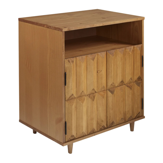
Step 11 WARNING Serious or fatal injuries can occur from furniture tipping over. To prevent the furniture from tipping over we recommend that it is permanently fixed to the wall. Wall anchor and hardware are included with this product. Please make sure hardware is suitable for your walls before installing, as different wall materials may require different types of anchors. - Page 12 Step 12 Assembly Complete! P.12...
Need help?
Do you have a question about the AF30HEN2D and is the answer not in the manual?
Questions and answers