Simplex 4020 Operating Manual
Fire indicator panel
Hide thumbs
Also See for 4020:
- Operating instruction (80 pages) ,
- Troubleshooting manual (34 pages) ,
- Installation instructions manual (14 pages)

Related Manuals for Simplex 4020


Summary of Contents for Simplex 4020
- Page 1 FIRE INDICATOR PANEL TYPE 4020 OPERATING MANUAL VERSION 2.0 FIRMWARE Document No: 4020-M010 1st February, 1997 Issue 2.0...
- Page 2 LED: Light Emitting Diode. MANUFACTURERS DETAILS APPROVALS: AUSTRALIAN STANDARDS AS1603.4 SSL CERTIFICATE OF COMPLIANCE NUMBER: 197 The 4020 Fire Indicator Panel is manufactured by: Simplex International Pty Ltd ACN: 008 435 443 140 Old Pittwater Road Brookvale N.S.W. 2100 Australia...
-
Page 3: Table Of Contents
3.5 KEYPAD CONTROLS ....................5 3.6 PROGRAMMING FUNCTIONS................5 3.7 COMMUNICATIONS PORT (OPTIONAL) ..............5 3.8 EXPANSION CARDS ....................5 4 AMENDMENTS TO 4020 OPERATOR MANUAL ............6 5 INTRODUCTION ......................9 5.1 OPERATOR FRONT PANEL ................. 11 6 ALARM CONDITIONS ....................14 6.1 ACKNOWLEDGING ALARMS................ - Page 4 Page iv 4020 OPERATORS MANUAL 9 PLACING INTO OPERATION................... 38 9.1 SETTING BATTERY CHARGER OUTPUT VOLTAGE:.......... 40 9.2 COMMISSIONING CHECKLIST................42 10 APPENDIX ......................44 10.1 ALARM VERIFICATION ZONE PROCESSING............ 44 10.2 AS1668 ZONE PROCESSING ................44 10.3 FAULT CONDITIONS................... 45 11 PROGRAMMING SHEETS ..................
- Page 5 4020 OPERATORS MANUAL Page v PANEL DETAILS panel sticker 4020 Panel supplied by Installation location Contract/Job Number As installed FIP System drawing number Panel Installation date Panel Commissioned date Maintenance Company Telephone Service Contact Document No: 4020-M010 1st February, 1997...
-
Page 7: Compatible Actuating Devices
4020 OPERATORS MANUAL Page 1 1 COMPATIBLE ACTUATING DEVICES The following detectors have been approved as compatible devices for use with the 4020 FIP. 1.1 SIMPLEX RANGE: 4098-9413 Heat detector Type A 4098-9414 Heat detector Type B 4098-9415 Heat detector Type C... -
Page 8: Apollo
Ionisation smoke detector 1.5 PANELECT/PANASONIC PFS-A Heat detector Type A PFS-B Heat detector Type B PFS-C Heat detector Type C PFS-D Heat detector Type D PFS-P Photoelectric smoke detector PFS-I Ionisation smoke detector Document No: 4020-M010 1st February, 1997 Issue 2.0... -
Page 9: Compatible Batteries
4020 OPERATORS MANUAL Page 3 2 COMPATIBLE BATTERIES The following series of batteries are compatible with the 4020 FIP: Power-Sonic PS12 series Sonnenschien A200 series Sonnenschien A300 series Yuasa NP series Document No: 4020-M010 1st February, 1997 Issue 2.0... -
Page 10: Specification
2 line by 40 character backlight Liquid Crystal Display with adjustable contrast control LED Status Indicators Common Alarm, Fault and Isolate Bell Isolated, ACF Isolated, Mains Power ON Audible Buzzer Alarm And Fault Indications Keypress feedback Document No: 4020-M010 1st February, 1997 Issue 2.0... -
Page 11: Keypad Controls
4020 OPERATORS MANUAL Page 5 SPECIFICATION (CONTINUED) 3.5 KEYPAD CONTROLS Fire Fighters Keypad NEXT, ACKNOWLEDGE, RESET, ISOLATE, BRIGADE TEST Service Technician 20 keys including:- Alarm Test, Fault Test, Keypad Isolate, Battery Test and Lamp test 3.6 PROGRAMMING FUNCTIONS Input Zone Type... -
Page 12: Amendments To 4020 Operator Manual
Page 6 4 AMENDMENTS TO 4020 OPERATOR MANUAL SECTION/PAGES DATE COMMENTS ECN No. ISSUE AMENDED AMENDED 16-09-91 Original 25-10-91 Various 1-02-97 Revised for Version 2.0 Firmware File: 4020M010.wp1 Document No: 4020-M010 1st February, 1997 Issue 2.0... - Page 13 4020 OPERATORS MANUAL Page 7 This page intentionally left blank Document No: 4020-M010 1st February, 1997 Issue 2.0...
- Page 14 Page 8 Figure 1 4020 FIP Document No: 4020-M010 1st February, 1997 Issue 2.0...
-
Page 15: Introduction
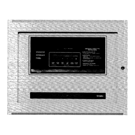
The Simplex 4020 fire indicator panel is a conventional programmable, microprocessor-controlled unit designed to meet the requirements of AS1603.4. The 4020 FIP can monitor from eight to forty eight fire detection zones and is permanently connected to the Fire Brigade alarm system. The fire detection... - Page 16 Page 10 FIGURE 1.2 OPERATOR FRONT PANEL Document No: 4020-M010 1st February, 1997 Issue 2.0...
-
Page 17: Operator Front Panel
The Text Window consists of two lines of text which describe the status of the system in four modes. Normal mode is the normal operational state of the panel. It shows: SIMPLEX AUSTRALIA - Time of day - Bat: OK Alarms: 0 Faults: 00 Isolated : 00... - Page 18 The bottom line shows the status of the circuit/zone at that time, the number of the displayed isolated circuit/zone, the total number of isolated circuits/zones, and the time the circuit/zone was isolated. Document No: 4020-M010 1st February, 1997 Issue 2.0...
- Page 19 The Isolate button is used to isolate any zone that cannot be ISOLATE reset. Non-resetable zones will continue to be registered on the display as an alarm until rectified. For example: SIMPLEX AUSTRALIA - Time of day - Bat: OK Alarms: 02 Faults: 00 Isolated : 02 NOTE: Once a zone has been isolated it cannot be reset using the main reset button.
-
Page 20: Alarm Conditions
1 of 2, or 1 of 3 depending on how many alarms there are. The time the alarm was activated is displayed on the right. Document No: 4020-M010 1st February, 1997 Issue 2.0... - Page 21 4020 OPERATORS MANUAL Page 15 STEP 3 Acknowledge the first alarm by pressing the ACKNOWLEDGE button which means, "I have read the alarm message and I understand it". An acknowledged indication (Ackd) is displayed on the left of ACKNOWLEDGE the bottom line.
-
Page 22: Resetting Zones In Alarm
Brigade will be called but the ancillary controls will not shut down and the fire alarm bell connected to the panel will not ring. Document No: 4020-M010 1st February, 1997 Issue 2.0... - Page 23 4020 OPERATORS MANUAL Page 17 The service company needs to be called to check why the zone circuits cannot be reset. This is done by the fire Brigade who have a register of every panel and the name of the service company.
-
Page 24: Fault Conditions
If there is only one fault (1 of 1), the fault light will go steady and the buzzer will silence. If there are two faulty zones, it is the initial fault (1 of 2) that is indicated and acknowledged. Document No: 4020-M010 1st February, 1997 Issue 2.0... - Page 25 4020 OPERATORS MANUAL Page 19 STEP 3 If the fault light is still flashing and the buzzer is still sounding, press the NEXT button to show the location and details of the second (2 of 2) fault. NEXT Press the ACKNOWLEDGE button to acknowledge the second ACKNOWLEDGE fault message (2 of 2).
-
Page 26: Buzzer Mute Facility
NOTE: The panel buzzer cannot be muted for alarm conditions. In the event of a fire alarm, the buzzer mute function is reset immediately and the panel buzzer will sound. Document No: 4020-M010 1st February, 1997 Issue 2.0... - Page 27 4020 OPERATORS MANUAL Page 21 This page intentionally left blank Document No: 4020-M010 1st February, 1997 Issue 2.0...
- Page 28 Page 22 Figure 1.3 Keypad function keys Document No: 4020-M010 1st February, 1997 Issue 2.0...
-
Page 29: Commissioning And Servicing
ALM LIST Presume the main display menu is in normal mode ie: SIMPLEX AUSTRALIA - Time of day - Bat: OK Alarms: 05 Faults: 05 Isolated : 05 To look at the alarms, press ALM LIST (1) and it will give access to that list of five alarms. - Page 30 NORMAL mode. Press the escape (ESC) key to return to normal display mode. NOTE: Using the main reset button, only acknowledged alarms can be reset. If they are isolated they cannot be reset except by using KEY 5 (RST). Document No: 4020-M010 1st February, 1997 Issue 2.0...
- Page 31 4020 OPERATORS MANUAL Page 25 ZONE DESCRIPTION LATCHING TYPE Noalm Non-alarm point Smoke detector zone with alarm verification Smoke Smoke Smoke detector zone N/L30 Non-latch AS1668 zone with 30 sec cycle N/L60 Non-latch AS1668 zone with 60 sec cycle V-Heat...
- Page 32 OUTPUT(8) and scroll through using the plus and minus keys and look at the output control devices. To exit the list press the escape (ESC) key. Key 9 is On/Off ON/OFF The On/Off (9) key has no function on this panel. Document No: 4020-M010 1st February, 1997 Issue 2.0...
- Page 33 4020 OPERATORS MANUAL Page 27 Plus (+) and Minus (-) keys Having selected a function, the plus(+) and minus(-) keys are used to scroll forward and backward through the list. − − − − Escape (ESC) key The escape key is used to return to the normal display from any of the functions which may have been selected.
-
Page 34: Alarm Test
Page 28 8.2 ALARM TEST The 4020 provides two Alarm test modes: Global Alarm Test mode: Simulates an alarm on all detector zones Individual zone alarm test mode: Simulates an alarm on a selected detector zone The following section describes the operation of the two modes. -
Page 35: Individual Zone Alarm Test
4020 OPERATORS MANUAL Page 29 STEP 3 Press the ACK+ (4) key to acknowledge each displayed alarm. If ACFs are not isolated, check that all the building controls work, the bell rings, the air conditioning will shut down, the magnetic door ACK+ holders will close fire doors, etc. - Page 36 Reset the circuits by pressing the ESC key to exit the alarm list and then press the RST (5) key or by using the main acknowledge/next/reset buttons. The following will be displayed: *** DETECTOR RESET IN PROGRESS *** Alarms: 00 Faults: 00 Isolated: 00 Document No: 4020-M010 1st February, 1997 Issue 2.0...
-
Page 37: Fault Test
4020 OPERATORS MANUAL Page 31 8.3 FAULT TEST STEP 1 Open the panel door and press FLT TEST. A fault condition will be simulated on every zone and the following message displayed: *** ALARM/FAULT TEST IN PROGRESS *** TEST Alarms: 00 Faults: XX Isolated: 00... - Page 38 STEP 3 To return to the normal display press escape (ESC). The display will now indicate the number of zones isolated. SIMPLEX AUSTRALIA - Time of day - Bat: OK Alarms: 00 Faults: 00 Isolated : XX Document No: 4020-M010 1st February, 1997 Issue 2.0...
-
Page 39: Operation Of Non-Latch As1668 Zones
4020 OPERATORS MANUAL Page 33 8.5 OPERATION OF NON-LATCH AS1668 ZONES Zones programmed as non-latching AS1668 zones must be in continual alarm before they operate their associated outputs. When operated, the outputs will track the alarm input and will be de-activated when the monitoring zone has been in a non-alarm condition for a period of either 30 or 60 seconds. -
Page 40: Brigade Test
Enter Brigade Test Type 0 to 7 STEP 3 Press escape (ESC) key twice to exit and return to the normal display mode Table 1.2 lists the available types of Brigade test options. Document No: 4020-M010 1st February, 1997 Issue 2.0... - Page 41 4020 OPERATORS MANUAL Page 35 BRIGADE DESCRIPTION No test facility Alarm relay ACF2 (Ct2) operates for 10 seconds Alarm relay ACF2 (Ct2) operates for 15 seconds Alarm relay ACF2 (Ct2) operates for 20 seconds Alarm relay ACF2 (Ct2) operates for 25 seconds...
-
Page 42: Walktest Mode
4020 panel. The WALKTEST incorporates an Auto Acknowledge/Auto Reset feature which allows one person to test the 4020 Fire Alarm System without the need for another person to be stationed at the control panel to acknowledge and reset alarm conditions... - Page 43 4020 OPERATORS MANUAL Page 37 NOTES: You can press KEY 5 (RST) key to abort the walk test at any time before the test timeout expires. All results of the Walk test are stored in the Alarm log and logged to a Serial Printer if connected.
-
Page 44: Placing Into Operation
Page 38 9 PLACING INTO OPERATION To place a correctly installed 4020 FIP into operation perform the following steps: STEP 1 Ensure that the mains isolate switch is OFF and batteries are disconnected. STEP 2 Ensure that 240V AC supply is connected to the panel from the mains distribution board. - Page 45 ACK+ TEST STEP 8 Program the panel in accordance with the instructions contained in the 4020 Programming Manual . STEP 9 Install the batteries and press the BAT TEST key to perform a battery test. NOTE: Ensure that the panel is turned ON and operating from mains power before connecting the batteries.
-
Page 46: Setting Battery Charger Output Voltage
Re-connect the batteries and press the CPU RESET switch to reset the system. CAUTION - POWERING REQUIREMENT When removing power from the panel, disconnect batteries FIRST and AC power last. When connecting power to the system, connect AC power FIRST and batteries last. Document No: 4020-M010 1st February, 1997 Issue 2.0... - Page 47 4020 OPERATORS MANUAL Page 41 FIGURE 1.4 MAIN PCB - BATTERY CHARGER ADJUSTMENT POINTS Document No: 4020-M010 1st February, 1997 Issue 2.0...
-
Page 48: Commissioning Checklist
External 24V DC fuse F5 fitted and rated at 2A Panel ratings label completed and affixed to panel Battery terminals insulated System wired to "as installed drawings" Log book installed in cabinet Document No: 4020-M010 1st February, 1997 Issue 2.0... - Page 49 4020 OPERATORS MANUAL Page 43 ITEM CHECKED Upon application of mains power, system powers- up correctly ALARM test function indicates alarms for all zone inputs FAULT test function indicates faults for all zone inputs Zone input delays function as programmed...
-
Page 50: Appendix
AS1668 - 30SEC: Minimum alarm period = 0 seconds Minimum non-alarm time period = 30 seconds. (ii) AS1668 - 60 SEC: Minimum alarm period 0 seconds and a continuos non-alarm period of 65 seconds. Document No: 4020-M010 1st February, 1997 Issue 2.0... -
Page 51: Fault Conditions
4020 OPERATORS MANUAL Page 45 10.3 Fault Conditions The table below lists the various fault messages displayed by 4020 FIP FAULT MESSAGE CAUSE OF FAULT FAULT RECTIFICATION Fire Alarm Zone Open Circuit on Fire Check Detectors in zone. Alarm Zone... -
Page 52: Programming Sheets
11 PROGRAMMING SHEETS Complete the programming sheets, which follow, in full. We suggest you use pencil so that future additions or changes may be simply made. Refer to the 4020 Programming Manaul for details on how complete the programming sheets. - Page 53 4020 OPERATORS MANUAL Page 47 This page intentionally left blank. Document No: 4020-M010 1st February, 1997 Issue 2.0...
- Page 54 Page 48 4020 OPERATORS MANUAL ZONE INPUT ZONE LABEL ZONE TYPE OUTPUTS OPERATED 1 |2 |3 | 4| 5| 6| 7| 8| 9|10|11|12|13|14|15|16|17|18|19|20|21|21|23|24|25|26|27 1 |2 |3 | 4| 5|6 |7 |8 Document No: 4020-M010 1st February, 1997 Issue 2.0...
- Page 55 4020 OPERATORS MANUAL Page 49 ZONE INPUT ZONE LABEL ZONE TYPE OUTPUTS OPERATED ZONE INPUT ZONE LABEL ZONE TYPE OUTPUTS OPERATED 1 |2 |3 | 4| 5| 6| 7| 8| 9|10|11|12|13|14|15|16|17|18|19|20|21|21|23|24|25|26|27 1 |2 |3 | 4| 5|6 |7 |8 Document No: 4020-M010 1st February, 1997 Issue 2.0...
- Page 56 Page 50 4020 OPERATORS MANUAL ZONE INPUT ZONE LABEL ZONE TYPE OUTPUTS OPERATED ZONE INPUT ZONE LABEL ZONE TYPE OUTPUTS OPERATED 1 |2 |3 | 4| 5| 6| 7| 8| 9|10|11|12|13|14|15|16|17|18|19|20|21|21|23|24|25|26|27 1 |2 |3 | 4| 5|6 |7 |8 Document No: 4020-M010 1st February, 1997 Issue 2.0...
- Page 57 4020 OPERATORS MANUAL Page 51 ZONE INPUT ZONE LABEL ZONE TYPE OUTPUTS OPERATED Document No: 4020-M010 1st February, 1997 Issue 2.0...
- Page 58 Page 52 4020 OPERATORS MANUAL ZONE INPUT ZONE LABEL ZONE TYPE OUTPUTS OPERATED ZONE INPUT ZONE LABEL ZONE TYPE OUTPUTS OPERATED 1 |2 |3 | 4| 5| 6| 7| 8| 9|10|11|12|13|14|15|16|17|18|19|20|21|21|23|24|25|26|27 1 |2 |3 | 4| 5|6 |7 |8 Document No: 4020-M010 1st February, 1997 Issue 2.0...
- Page 59 4020 OPERATORS MANUAL Page 53 ZONE INPUT ZONE LABEL ZONE TYPE OUTPUTS OPERATED ACF OUTPUT CIRCUIT LABEL OPERATED BY DOOR ISOLATE OUTPUT DELAY 1 |2 |3 | 4| 5|6 |7 |8 |9 |10|11|12|13|14|15|16|17|18|19|20|21|21|23|24|25|26|27 YES/NO | sec YES/NO | sec YES/NO...
- Page 60 Page 54 4020 OPERATORS MANUAL ACF OUTPUT CIRCUIT LABEL OPERATED BY DOOR ISOLATE OUTPUT DELAY YES/NO | sec YES/NO | sec YES/NO | sec YES/NO | sec YES/NO | sec YES/NO | sec YES/NO | sec YES/NO | sec YES/NO...
- Page 61 4020 OPERATORS MANUAL Page 55 ACF OUTPUT CIRCUIT LABEL OPERATED BY DOOR ISOLATE OUTPUT DELAY YES/NO | sec YES/NO | sec YES/NO | sec YES/NO | sec YES/NO | sec YES/NO | sec YES/NO | sec YES/NO | sec YES/NO...
- Page 62 Page 56 4020 OPERATORS MANUAL ACF OUTPUT CIRCUIT LABEL OPERATED BY DOOR ISOLATE OUTPUT DELAY YES/NO | sec YES/NO | sec YES/NO | sec YES/NO | sec YES/NO | sec YES/NO | sec YES/NO | sec YES/NO | sec YES/NO...
Need help?
Do you have a question about the 4020 and is the answer not in the manual?
Questions and answers