Advertisement
Quick Links
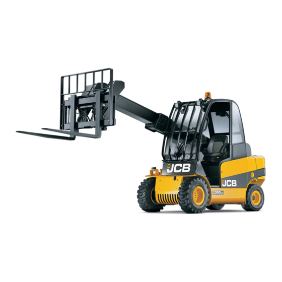
LPG TLT
QUICK REFERENCE GUIDE
This Quick Reference Guide DOES NOT replace the Operators
Manual. You MUST read ALL the disclaimers and safety and other
instructions in the Operators Manual before initially operating this
product. Accordingly, no legal claims can be entertained based on
the data, illustrations or descriptions in this Quick Reference Guide.
BEST PRACTICES
Static Dimensions
1.
Carry a load as low as possible while maintaining good
visibility.
2.
Forks should be tilted back when in transport – with or
without a load, cradle the load.
3.
Fork tips should be on the ground when unit is parked.
Static Dimensions
Moving Machine
Lifting Machine
Tie-Down Points
A.
Lifting point x 4
A.
B.
Padding
Cab and Switch Panel
Coolant Temperature Gauge
Transmission Drive Lever
Securing method
A.
Steering wheel
B.
Lift arm controls
C.
Coolant temperature gauge
D. Instrument panel
E.
Console switches
F.
Seat
G. Accelerator pedal
H. Inching pedal
J.
Transmission drive lever
A.
211.9 °F – Warning lamp on
B.
220.9 °F – Reduced engine power
C.
229.8 °F – Critical stop lamp
illuminates. Further reduction in
the engine power
A.
Lever
B.
Twist grip
C.
Front differential indicator lamp
Revision 1.0
1/6/2021
Instrument Panel
A.
Amber warning
B.
Critical stop (red)
C.
Engine coolant temperature (red)
D. Not used
E.
Transmission oil temperature (red)
F.
Engine oil pressure (red)
G. Alternator charge (red)
H. Park brake (red)
J.
Air filter blocked
K.
Hydraulic filter
L.
Seat switch
M. Hour meter / time to service / service due / fault code display
Start Up Sequence
Access additional information
www.servicepro.jcb.com
Advertisement

Related Manuals for jcb LPG TLT Series


Summary of Contents for jcb LPG TLT Series
- Page 1 229.8 °F – Critical stop lamp illuminates. Further reduction in the engine power Transmission Drive Lever Moving Machine Lifting Machine Tie-Down Points Lever Twist grip Front differential indicator lamp Lifting point x 4 Securing method Padding Access additional information www.servicepro.jcb.com Revision 1.0 1/6/2021...
-
Page 2: Control Layout
Control Layout Service Points Install Changezee Quickhitch Attachment Boom Controls – Regular Pattern Air intake Radiator cap Radiator D. Coolant expansion tank Battery isolator Engine oil filler cap Carriage Controls – Regular Pattern G. Battery H. Engine oil dipstick Window washer fluid tank Install Fork Attachment Hydraulic oil level indicator, hydraulic oil filler cap Access Covers... - Page 3 Insert Isolator Key Fasten Seat Belt Set to Neutral Turn clockwise Climb into the cab and Ensure the machine is not in fasten/adjust the seat belt gear and the parking brake is on Insert Key and Start Operate Hydraulics Connect LPG Tank Turn the key to position II until Operate hydraulics to make Should be positioned in the...
- Page 4 Align the Machine Engage Attachment Stop the Machine Align the carriage with the Engage forward until pivot shaft Park on dry level ground attachment below the level of touches the attachment. hooks (B) Engage parking brake and raise arm so pivot shaft (A) engages hooks (B) Engage Locking Pins With the Park brake applied,...
- Page 5 Attach the Forks (1) Attach the Forks (2) Stop the Machine Position the forks in the central Slide each fork along the Park on dry level ground position, allowing the hooks (D) carriage away from the central to engage with upper carriage position, ensuring the upper and overlap lower removal (D) and lower (B) positions are...
- Page 6 Remove Locking Pins Engage the Bucket (1) Stop the Machine Remove locking pins (C) and Raise boom while crowding Park on dry level ground align with center of hitch plate back to engage carriage onto (E). Extend boom until hitch the lips (B).