Table of Contents
Advertisement
Quick Links
Advertisement
Table of Contents

Subscribe to Our Youtube Channel
Related Manuals for Eachine E150


Summary of Contents for Eachine E150
- Page 1 User Manual E150...
- Page 2 Content Page Introduction Contents List Notice Warning Additional Safety Precautions and Warnings Helicopter Specifications Warning and Guidance of Battery Usage Battery Charging Notice Before Flight Pairing With Transmitter Throttle Curve and Pitch Curve Initial Flight Setup Flight Control Board Interface Diagram About the Transmitter Flight Control Board Adjustment Troubleshooting...
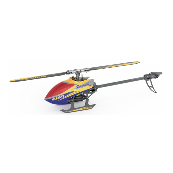
- Page 3 For up-to-date product literature, please visit mechanism. With improved aerodynamics, the blades deliver outstanding power www.eachine.com. and stability. The state of the art Flight Control Board utilises the latest technological improvements and provides 3D and 6G modes. Extreme aerobatic stunts are possible in 3D mode.
- Page 4 Helicopter Specifications Warning 1. For maximum safety, please monitor the battery while charging. Length 330 mm 2. Please do not allow children to carry out the charging by themselves but ensure Height 105mm adult supervision is available at all times. Weight 181g 3.
- Page 5 Initial Flight Setup Notice: If you are not familiar with the controls of the E150, please take a few minutes to get 1. When the transmitter is turned on and the throttle hold switch is in the ON position, familiar with them and then try your first flight.
- Page 6 About the Transmitter Flight Control Board Adjustment 1)Servo Centering Adjustment Note: The product has been adjusted and inspected before leaving the factory. The user needs to re-adjust the servo centering after replacing the servo or related 6CH/IDLE Switch accessories. To ensure safety, disconnect the main motor power during adjustment to avoid personal injury caused by motor rotation.
- Page 7 Troubleshooting Illustrated Parts Diagram Problem Cause Solution LED on receiver flashes constantly Transmitter is not bound to receiver. Carry out pairing (Refer to P.5, with no response after transmitter Pairing of the transmitter and receiver Pairing to Transmitter). is switched on. failed.
- Page 8 Part Name: Servo Swashplate Secondary Linkage Set Servo Main Shaft Set Servo Mounting Plate Part No: 2.32.01.E150-009 Part No: 2.32.01.E150-010 Part Part No: 2.32.01.E150-011 Part No: 2.32.01.E150-012 Canopy Mounting Posts Part Name: Canopy Part Name: Main Shaft Set Name: Servo Mounting Plate...
Need help?
Do you have a question about the E150 and is the answer not in the manual?
Questions and answers