Simrad ST90 Harbour Acceptance Test
Fish-finding sonar
Hide thumbs
Also See for ST90:
- Installation manual (536 pages) ,
- Operator's manual (190 pages) ,
- Quick start manual (76 pages)
Table of Contents
Advertisement
Quick Links
This is the Harbour Acceptance Test for the Simrad ST90 Fish-finding
sonar.
The purpose of this Harbour Acceptance Test is to verify that the
ST90 system provided to the vessel is correctly installed, and fully
functional. It is then ready for the Sea Acceptance Test. When all the
tasks have been done, the report form must be signed by the relevant
parties. The completed document then becomes the official report.
Vessel/Customer
Serial numbers (if applicable)
Processor Unit
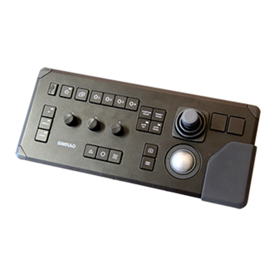
Operating Panel
Transceiver Unit
Hull Unit
Transducer
Simrad ST90
Fish-finding sonar
Harbour Acceptance Test
May 2020 © Kongsberg Maritime AS
442729/A
Advertisement
Table of Contents

Related Manuals for Simrad ST90


Summary of Contents for Simrad ST90
- Page 1 Simrad ST90 Fish-finding sonar Harbour Acceptance Test This is the Harbour Acceptance Test for the Simrad ST90 Fish-finding sonar. The purpose of this Harbour Acceptance Test is to verify that the ST90 system provided to the vessel is correctly installed, and fully functional.
- Page 2 If you require maintenance or repair, contact your local dealer. You can also contact us using the following address: simrad.support@simrad.com. If you need information about our other products, visit https: //www.simrad.com. On this website you will also find a list of our dealers and distributors. Kongsberg Maritime AS www.kongsberg.com...
-
Page 3: Table Of Contents
Visual inspection of the Transceiver Unit................22 Visual inspection of the hull unit ..................24 Environmental inspection of the Transceiver Unit ............26 Making sure that all ST90 cables are properly connected ..........27 TESTING THE ST90 OPERATIONAL FUNCTIONALITY....29 Checking the transducer lower and hoist functionality............29 Bridge steps ......................30... - Page 4 Simrad ST90 Verifying vessel origin and ship dimensions ..............49 Verifying the installation parameters for the transducer ..........51 Verifying the installation parameters for the global positioning system (GPS) antenna ........................52 Verifying the installation parameters for the motion reference unit (MRU) ....54 CUSTOMER ACCEPTANCE FORM ..........
-
Page 5: Introduction
Introduction Introduction Topics Purpose, page 6 Personnel and location, page 6 Referenced documents, page 6 Tools and test equipment, page 7 442729/A... -
Page 6: Purpose
This is the Harbour Acceptance Test for the Simrad ST90 Fish-finding sonar. The purpose of this Harbour Acceptance Test is to verify that the ST90 system provided to the vessel is correctly installed, and fully functional. It is then ready for the Sea Acceptance Test. -
Page 7: Tools And Test Equipment
Introduction Note Unless specified in the applicable procedure(s), the ST90 publications listed here are not required during this Harbour Acceptance Test. All the document numbers refer to the English version of each publication. End user manuals • : 442704 Reference Manual and On-line Help •... -
Page 8: Acceptance Test Summary
Simrad ST90 Harbour Acceptance Test Acceptance test summary The purpose of this Harbour Acceptance Test is to verify that the ST90 system provided to the vessel is correctly installed, and fully functional. This acceptance test summary is provided to offer an overview of the functions and items that need to be tested. -
Page 9: Hardware And Software Registration
Hardware and software registration Hardware and software registration Topics Verification of previously tested items, page 10 Software items, page 11 Hardware items, page 12 442729/A... -
Page 10: Verification Of Previously Tested Items
Verification of previously tested items Neither user interface software nor hardware units have been changed on this ST90 system since the Factory Acceptance Test. For this reason, the registration tables have not been filled out. Date and signature... -
Page 11: Software Items
Every software program that is provided as a part of the ST90 delivery must be registered. Part number and software version must be registered. When software media (USB flash drive, CD, DVD etc) is provided, the part number of the media and the ST90 software version provided on the media must be registered. -
Page 12: Hardware Items
Serial number Revision Fill in the make, model and serial number for each unit that is provided with the ST90 delivery. If applicable, add the part number. The unit contains neither circuit boards nor modules that need to be identified separately. -
Page 13: Transceiver Unit
This is the part number on the unit label. Transceiver Unit The Transceiver Unit provided with the ST90 delivery must be uniquely identified. Make, model, part number and serial number must be registered. The Transceiver Unit contains circuit boards and modules that must be recorded separately. -
Page 14: Operating Panel
2960L Ethernet switch is not used with this delivery, fill in information about the replacement type in the empty row. This is the part number on the unit label. Operating Panel The Operating Panel provided with the ST90 delivery must be uniquely identified. Make, model, part number and serial number must be registered. 442729/A... -
Page 15: Hull Unit
This is the part number on the unit label. Hull Unit The hull unit provided with the ST90 delivery must be uniquely identified. If possible, type, part number and serial number must be registered. Several different hull units are available for the ST90, each with different characteristics. Only one hull unit is supplied with the delivery. -
Page 16: Transducer
Simrad ST90 Harbour Acceptance Test Transducer The transducer provided with the ST90 delivery must be uniquely identified. Note The transducer is not accessible during the Harbour Acceptance Test. The hardware registration is then omitted. Transducer Part number Serial number Revision... -
Page 17: Visual Inspection
Environmental inspection of the Transceiver Unit, page 26 Making sure that all ST90 cables are properly connected, page 27 Visual inspection of the display A visual inspection of the ST90 display is required to verify that the unit has not been physically damaged during the installation. Prerequisites The ST90 is installed as specified in the ST90 Installation manual. - Page 18 Simrad ST90 Harbour Acceptance Test Make sure that the structure to which the display is fastened is substantial enough to hold the unit securely under all operating conditions. If applicable, make sure that the display (or the display mounting bracket) is bolted or welded securely to the deck and/or bulkhead.
-
Page 19: Visual Inspection Of The Processor Unit
The display is properly grounded. Date and signature: Visual inspection of the Processor Unit A visual inspection of the ST90 Processor Unit is required to verify that the unit has not been physically damaged during the installation. Prerequisites The ST90 is installed as specified in the ST90 Installation manual. The ST90 is turned off. - Page 20 Simrad ST90 Harbour Acceptance Test Make sure that all welds and brackets have been painted with the correct preservation medium to prevent corrosion. Make sure that the unit is not physically damaged, and that the paint-work is clean without dents or scratches.
-
Page 21: Visual Inspection Of The Operating Panel
A visual inspection of the Operating Panel is required to verify that the unit has not been physically damaged during the installation.. Prerequisites The ST90 is installed as specified in the ST90 Installation manual. The ST90 is turned off. You need the following equipment: • Multimeter Procedure Make sure that the unit’s serial number has been recorded in the list of hardware... -
Page 22: Visual Inspection Of The Transceiver Unit
A visual inspection of the Transceiver Unit is required to verify that the unit has not been physically damaged during the installation. Prerequisites The ST90 is installed as specified in the ST90 Installation manual. The ST90 is turned off. You need the following equipment: • Multimeter Procedure Make sure that the unit’s serial number has been recorded in the list of hardware... - Page 23 Visual inspection Make sure that the welds and support brackets to which the unit is fastened are substantial enough to hold the it securely under all operating conditions. Make sure that all welds and brackets have been painted with the correct preservation medium to prevent corrosion.
-
Page 24: Visual Inspection Of The Hull Unit
It is also important to check that the unit has been installed correctly. Prerequisites The ST90 is installed as specified in the ST90 Installation manual. The ST90 is turned off. You need the following equipment: • Multimeter Procedure Make sure that the unit’s serial number has been recorded in the list of hardware... - Page 25 Make sure that the transducer cables can move freely when the transducer is lowered and hoisted. Repeat the inspection of the transducer cables when the ST90 is turned on and put to operational use. Make sure that the unit is firmly connected to ship's ground.
-
Page 26: Environmental Inspection Of The Transceiver Unit
Transceiver Unit. An environmental inspection of the Transceiver Unit is required to verify the quality of the sonar room. Prerequisites The ST90 is installed as specified in the ST90 Installation manual. You need the following equipment: • Thermometer •... -
Page 27: Making Sure That All St90 Cables Are Properly Connected
You need the following equipment: • Cable tester • Multimeter Context All cabling is described in the Cable layout and interconnections chapter in the ST90 Installation Manual. Refer to the cable plan, the cable list and the basic cable requirements. 442729/A... - Page 28 Simrad ST90 Harbour Acceptance Test Procedure For each cable that is in used on the ST90: Make sure that the cable has been installed as specified in the ST90 Installation Manual. Note Pay special attention to signal cables. These must not be installed too close to power cables.
-
Page 29: Testing The St90 Operational Functionality
The hull unit provided with the ST90 is designed to lower the transducer down below the ship’s hull when the ST90 shall be used. This is a key functionality of the ST90. It is very important that the hoist/lower function is tested before the ST90 is put to operational use. -
Page 30: Bridge Steps
The hull unit provided with the ST90 is designed to lower the transducer down below the ship’s hull when the ST90 shall be used. This is a key functionality of the ST90. It is very important that the hoist/lower function is tested before the ST90 is put to operational use. - Page 31 Testing the ST90 operational functionality On the Operating Panel, press Middle While the transducer is moving the indicator lamp flashes, and an audible signal is sounded. When the requested position has been reached, the indicator lamp is lit, and the audible signal stops.
-
Page 32: Sonar Room Steps
The hull unit provided with the ST90 is designed to lower the transducer down below the ship’s hull when the ST90 shall be used. This is a key functionality of the ST90. It is very important that the hoist/lower function is tested before the ST90 is put to operational use. - Page 33 When the transducer shaft stops, verify that the correct upper position has been reached. 10 [Bridge] Notify the sonar room to do the next step. 11 Locate the (S302). Set the switch to position STOP. Hoist/Lower Switch 12 [Bridge] Power down the ST90. 442729/A...
-
Page 34: Testing The User Interface To Verify Basic Functionality
A functional test is done with the ST90 system assembled as a complete product. Prerequisites The ST90 has been set up with its hardware units connected as specified in the ST90 Installation manual. • The ST90 system is turned on and operates normally. -
Page 35: Checking The St90 Operation By Means Of The Bite Functionality
BITE and verification of the ST90 hardware components. Prerequisites The ST90 has been set up with its hardware units connected as specified in the ST90 Installation manual. • The ST90 system is turned on and operates normally. • The ST90 is in Normal mode, but is set to Off to prevent transmissions. - Page 36 (Built-In Test Equipment) functionality, you can easily determine BITE if the ST90 hardware is operational. And most important, you can make sure that all the transceivers channels and the transducer elements are functional. To open the different pages in the (Built-In Test Equipment) dialog box, use the large "buttons"...
- Page 37 Select to open the page. Transducer page presents all the elements that are used in the ST90 transducer. Transducer The presentation attempts to organize the elements in the same manner as in the physical transducer. The transceiver boards are shown as "buttons". Select a transceiver board to highlight the elements that are physically connected to the board.
- Page 38 If faulty channels are grouped together on the transducer face, this may cause a visible defect in the ST90 presentation. If they are scattered, the visible defect may be a lot harder to see. In all cases, the echoes from the neighbouring channels cause an interpolation that will restore a lot of the degraded presentation.
- Page 39 Testing the ST90 operational functionality Result Requirements Results The maximum number of unserviceable elements is 3. Date and signature: Further requirements If the noise level is higher than specified, you must check the reason(s) for this. • Check the grounding of the Transceiver Unit.
-
Page 40: Testing The Interfaces With Peripheral Devices
Prerequisites The ST90 is installed as specified in the ST90 Installation manual. • The sensor is connected to a communication port on the ST90. The sensor is on and in normal operation. • The interface port is set up with the correct communication parameters. - Page 41 The properties of each of the available communication ports are defined on the I/O Setup page. The page allows your ST90 to communicate with external Sensor Installation sensors and systems. To make sure that the information from the "most reliable" sensors are used by the ST90, use the page to define a datagram priorities.
-
Page 42: Verifying The Communication With Speed Log
Date and signature: Verifying the communication with speed log In order to operate correctly, the ST90 requires input from a speed log. The vessel speed is shown on the top bar if you have enabled this in the dialog box. The Display Options communication with the sensor is tested. - Page 43 Context Note The speed input is essential for ST90 operation. Without speed information, the ST90 will neither be able to present correct navigational information, nor compensate for vessel movements. This lack of compensation will prevent the ST90 from providing correct echo information.
-
Page 44: Verifying The Communication With The Course Gyro
Prerequisites The ST90 is installed as specified in the ST90 Installation manual. • The sensor is connected to a communication port on the ST90. The sensor is on and in normal operation. • The interface port is set up with the correct communication parameters. - Page 45 Context Note The input from a course gyro is essential for ST90 operation. Without the input from a course gyro, the ST90 will not be able to present correct navigational information.This lack of compensation will prevent the ST90 from providing correct echo information.
-
Page 46: Verifying The Communication With The Motion Reference Unit (Mru)
Prerequisites The ST90 is installed as specified in the ST90 Installation manual. • The sensor is connected to a communication port on the ST90. The sensor is on and in normal operation. • The interface port is set up with the correct communication parameters. - Page 47 Context A motion reference unit (MRU) measures the vessel’s pitch and roll movements in the sea. The information provided by the motion sensor is used by the ST90 to stabilize the beams and the echo presentation. Procedure Open the menu.
- Page 48 Display Options Note In order to read the motion compensation values, the ST90 must be "pinging". As long as the vessel is in port, you can not expect major changes in the values. If possible, use another instrument to verify that the information provided by the ST90 is correct.
-
Page 49: Verifying The Installation Parameters
ST90 software. Prerequisites For accurate location of the ship dimensions, you need the detailed vessel drawings. Neither tools nor instruments are required. The ST90 system is turned on and operates normally. Context It is common practice to place the Ship Origin at the same position as the motion reference unit (MRU). - Page 50 Installation Result Ship Dimensions Length Width Vessel origin X Offset Y Offset Z Offset Requirements Results The ship dimensions are entered in the ST90. All values are correct. All values are recorded in the relevant table. Date and signature: 442729/A...
-
Page 51: Verifying The Installation Parameters For The Transducer
"forward" mark on the transducer shaft sleeve - and thus also "forward" on the transducer - may not point forward at all, but several degrees off the centre line. To obtain accurate ST90 presentations, this misalignment must be adjusted by changing the installation parameters. -
Page 52: Verifying The Installation Parameters For The Global Positioning System (Gps) Antenna
Verifying the installation parameters for the global positioning system (GPS) antenna Information from a few key sensors are vital for the ST90 accuracy. In order to achieve maximum accuracy, the physical locations of these sensors - normally referred to the Ship Origin - must be recorded in the ST90 setup. - Page 53 Context The physical location of the global positioning system (GPS) antenna relative to the transducer is required to allow the ST90 to show the correct navigational information in the ST90 presentation. The locations of the transducer and the Global Positioning System (GPS) antenna must be referenced to a common Ship Origin.
-
Page 54: Verifying The Installation Parameters For The Motion Reference Unit (Mru)
The physical location of the motion reference unit (MRU) relative to the transducer is required to allow the ST90 to adjust for roll and pitch as accurately as possible. This task is only applicable is you are using an external motion reference unit on your ST90. - Page 55 - and other GPS systems - allow you to define the MRU location in the positioning system. If this is done, the MRU offset values in the ST90 must be set to 0 (zero) to avoid "dual compensation". The rotation information is normally not recorded by the positioning system, and must therefore be defined in the ST90.
-
Page 56: Customer Acceptance Form
When this test procedure has been completed with all relevant signatures and applicable forms filled in, the document must be sent to the Simrad Support Department at Strandpromenaden 50, P.O.Box 111, 3191 Horten, Norway. Alternatively, scan all the pages to PDF using minimum 200 DPI resolution, and send the file to simrad.support@simrad.com. -
Page 57: Secondary Procedures
Setting up the Operating Panel (Mk2) The Operating Panel offers all necessary control functions for normal operation of the ST90. Before it can be put to use, the Operating Panel must be configured to permit Ethernet communication between the panel and the Processor Unit. - Page 58 Simrad ST90 Harbour Acceptance Test To set up the Ethernet communication, you must define the IP address for the panel, and identify the Processor Unit in the panel software. These settings allow you to use more than one Operating Panel on the Processor Unit. You can also control more than one Processor Unit from a single Operating Panel.
- Page 59 Write down the information. Close the window. Command Prompt Select the adapter that the Operating Panel is connected to. On the ST90, the Ethernet adapter is named Simrad Connect. Prepare the Operating Panel for use. Make the following preparations. Connect the power cable from the Operating Panel to the power outlet on the uninterruptible power supply (UPS).
- Page 60 Make sure that the blue indicator is lit, and check that you can move the cursor on the screen. On the Processor Unit desktop, double-click the ST90 icon to start the program. Wait until the ST90 operates normally. Press and hold...
- Page 62 ©2020 Kongsberg Maritime...
Need help?
Do you have a question about the ST90 and is the answer not in the manual?
Questions and answers