Simrad ST90 Operator's Manual
Fish finding sonar
Hide thumbs
Also See for ST90:
- Installation manual (536 pages) ,
- Quick start manual (76 pages) ,
- Harbour acceptance test (62 pages)

Subscribe to Our Youtube Channel
Related Manuals for Simrad ST90


Summary of Contents for Simrad ST90
- Page 1 Operator Manual Simrad ST90 Fish finding sonar TECHNOLOGY FOR SUSTAINABLE FISHERIES www.simrad.com...
- Page 3 Simrad ST90. This manual is intended for all regular users of the ST90. Due to the nature of the descriptions and the level of detail provided by this manual, it is well suited for those who use the ST90 on a daily basis, and have access to expert users for advice.
- Page 4 Support information If you require maintenance or repair, contact your local dealer. You can also contact us using the following address: simrad.support@simrad.com. If you need information about our other products, visit https: //www.simrad.com.
-
Page 5: Table Of Contents
GETTING STARTED ..............18 Operating Panel description....................19 Starting normal operation ..................... 22 Turning on the ST90 for normal use ................22 Getting to know the user interface ................24 Getting to know presentation modes and views ............26 Selecting Normal mode to start "pinging"..............30 Adjusting the radius of the search area ............... - Page 6 Simrad ST90 Selecting Inactive mode ....................54 Setting up the ST90 for maximum echo refresh rate........... 55 Transmitting single pings .................... 56 Transmitting with fixed-time intervals ................ 57 Adjusting the output power to match varying conditions ........... 58 Selecting the best operating frequency................ 59 Controlling the gain and range settings ................
- Page 7 Selecting menu language..................... 97 Hiding the menu system ....................98 Placing the menu on the left side of the ST90 presentation ........99 Selecting the information to appear on the top bar ............. 99 Enabling Coordinated Universal Time (UTC) on the bottom bar ......100 Selecting which tooltips to appear in the user interface ..........
- Page 8 Setting up the interface for course gyro input ............136 Configuring the sensor interface................138 Setting up the input from a motion reference unit (MRU)........140 Setting up the ST90 in a synchronized system............142 MENU SYSTEM ................. 145 About the menus and menu buttons..................146 Using the “smart”...
-
Page 9: About This Manual
ST90 on a daily basis, and have access to expert users for advice. We assume that you are familiar with the basic acoustic principles of sound in water. We also expect that you have some experience with sonar operation. - Page 10 Simrad ST90 Operator Manual Online information All end-user manuals provided for operation and installation of your Simrad ST90 can be downloaded from our website. Our website also provides information about other Simrad products. • https://www.simrad.com/st90 457420/A...
-
Page 11: Simrad St90
Before you turn on the ST90, make sure that you have sufficient water depth to lower the transducer! Caution You must never turn on the ST90 when the ship is in dry dock. The transducer may be damaged if it transmits in open air. 457420/A... - Page 12 Note If you turn off the ST90 by means of the on/off switch on the Processor Unit you may damage the software and the interface settings used to communicate with external devices. Manual operation of the hull unit In the event of improper operation, the powerful electric motor on the hull unit may cause serious damage to the equipment and/or injury to personnel.
-
Page 13: System Description
• Do not damage the transducer cables, and avoid exposure to sharp objects. System description The Simrad ST90 is a long range and low frequency fish finding sonar with a 360 degrees coverage. The ST90 is designed for medium and large sized fishing vessels. - Page 14 • They increase the range and resolution, and offer a vertical view with additional details and a clearer picture. • They make the ST90 even more ideal when you need to search for fish close to the sea bottom, or close to the surface, at long ranges.
-
Page 15: System Diagram
Simrad ST90 System diagram The system diagram identifies the main components of a basic ST90 system. Only the main connections between the units are shown. Detailed interface capabilities and power cables are not shown. Display (The second display is optional.) -
Page 16: General Safety Rules
Safety is important. The safety precautions must be followed at all times during installation and maintenance work. WARNING The ST90 operates on 115 VAC and/or 230 VAC at 50/60 Hz. This voltage is lethal! You must never work alone on high-voltage equipment! The hull unit is powered by a 3-phase high voltage. -
Page 17: Support Information
Simrad ST90 Support information If you need technical support for your Simrad ST90 you must contact your local dealer, or one of our support departments. A list of all our offices and dealers is provided on our website. You can also contact our main support office in Norway. - Page 18 Simrad ST90 Operator Manual • : Kongsberg Underwater Technology Inc / Simrad Fisheries Company name • : 19210 33rd Ave W, Suite A, Lynnwood, WA 98036, USA Address • : +1 425 712 1136 Telephone • : +1 425 712 1193 Telefax •...
- Page 19 Simrad ST90 China • : Kongsberg Maritime China Ltd Company name • : 555 Chuanqiao Road, China (Shanghai) Pilot Free Trade Zone, 201206, China Address • : +86-21-3127-9888 Telephone • : +86-21-3127-9555 Telefax • https://www.simrad.com Website • simrad.china@simrad.com E-mail address...
-
Page 20: Getting Started
Simrad ST90 Operator Manual Getting started Topics Operating Panel description, page 19 Starting normal operation, page 22 Basic operating procedures, page 40 457420/A... -
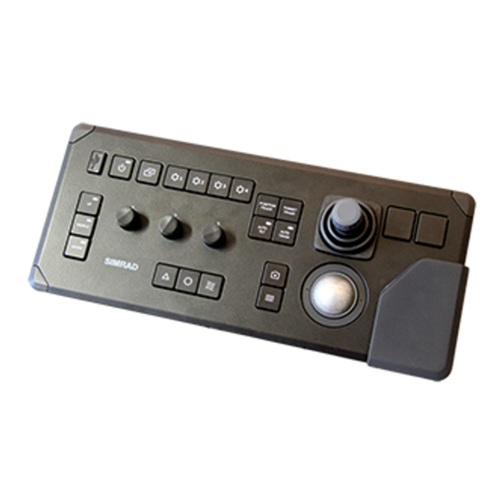
Page 21: Operating Panel Description
• Before you turn on the ST90, make sure that you have sufficient water depth to lower the transducer! • You must never turn on the ST90 when the ship is in dry dock. The transducer may be damaged if it transmits in open air. - Page 22 Button Options function to each button on the Operating Panel. : Press this button to make a copy of the current ST90 presentation. You Screen Capture can choose either a single screen capture or a sequence with multiple screen captures.
- Page 23 Trackball Note The ST90 supports two different operating panels. These are referred to as "Mk1" and "Mk2". In this publication all descriptions and references are related to "Mk2". Before you can change the settings related to a view, you must click inside the view to activate it.
-
Page 24: Starting Normal Operation
Adjusting the horizontal direction of the sonar beam, page 37 Turning off the ST90, page 39 Turning on the ST90 for normal use In order to use the ST90, you must first turn it on. To turn on the ST90 use the button Power on the Operating Panel. - Page 25 Main Operation The icon is flashing to indicate that even if the ST90 is turned on, "pinging" is disabled. The ST90 is in Normal mode, but is set to Off to prevent transmissions. TX Power This is for safety reasons.
-
Page 26: Getting To Know The User Interface
By default, the ST90 presentation covers the entire screen. Context All echoes offered by the ST90 are shown in rectangular views. Each view has a specific purpose, and it can be set up with independent operational settings. Combinations of these views are organized in presentation modes, which you can select on the bottom bar. - Page 27 Move the cursor to the top bar, and investigate the functions provided. The ST90 top bar is located at the top of the display presentation and stretches from the far left to the far right. The top bar gives you fast access to key functionality and navigational information.
-
Page 28: Getting To Know Presentation Modes And Views
Move the cursor to the bottom of the ST90 presentation. The bottom bar is located at the bottom of the ST90 presentation and stretches from the far left to the far right. It allows you to choose presentation mode (view combinations). - Page 29 • Catch • Echogram • Plane With the various beams provided by the ST90, it may be difficult to understand the concept. How do these beams "behave" in the water? By means of a graphic presentation, the Beam dialog box attempts to give you a better understanding of how the acoustic Visualization beams are transmitted into the water.
- Page 30 Cosmetics At the bottom of the ST90 presentation, select a suitable presentation mode, and activate the Vertical view. The view shows you a "vertical slice" of the echo data. The slice is made at the current bearing.
- Page 31 Fishing Gear Setup side to Port or Starboard. At the bottom of the ST90 presentation, select a suitable presentation mode, and activate the Catch view. Use the information in the Catch view to monitor the progress of the purse seine operation.
-
Page 32: Selecting Normal Mode To Start "Pinging
Related topics Starting normal operation, page 22 Selecting Normal mode to start "pinging" In order to transmit ("ping") you must set the ST90 to Normal operating mode. This is the default mode when the ST90 is turned on. Context function controls the operating mode of the ST90. You can set it to Normal, Operation Replay or Inactive. - Page 33 Getting started Caution You must never start ST90 transmissions (pinging) when the ship is in dry dock. The transducer may be damaged if it transmits in open air. Once started, the ST90 transmissions are controlled by the Transmission Mode functions.
-
Page 34: Adjusting The Radius Of The Search Area
On the ST90, this is referred to as range. Context setting defines how "far" you wish the ST90 to detect echoes. In other words, you Range specify the horizontal or vertical distance from the vessel to the outer edge of the search area. -
Page 35: Adjusting The Echo Sensitivity
Adjusting the echo sensitivity Some echoes are weak while others are stronger. To compensate for this it is often necessary to adjust the sensitivity of the ST90. This adjustment is commonly referred to as gain. Context You can compare this gain setting with the volume control on your car radio. When the gain is increased, the echoes will appear stronger. - Page 36 Each switch can be assigned a function related to range, gain or bearing. Investigate the functionality provided on the page. This page Operating Panel is located in the dialog box. Installation Optionally: Observe the menu. Main Its default location is on the right side of the ST90 presentation. 457420/A...
-
Page 37: Changing The Vertical Angle Of The Sonar Beams
Release the mouse button when requested value is shown. Select the middle of the button to open it. If you have a keyboard connected to the ST90, you can type the requested value. Open the button and select... - Page 38 Once again you can activate the RCG function to improve the reading. With the various beams provided by the ST90, it may be difficult to understand the concept. How do these beams "behave" in the water? By means of a graphic presentation, the...
-
Page 39: Adjusting The Horizontal Direction Of The Sonar Beam
Starting normal operation, page 22 Adjusting the horizontal direction of the sonar beam The Horizontal view in the ST90 presentation covers the entire 360° omnidirectional sector For the other views you must define the horizontal direction of the beam. Context In the Horizontal view the current bearing is shown with a continuous line pointing out from the vessel position. - Page 40 In a Horizontal view, select the bearing line and drag it sideways. Optionally: Observe the menu. Main Its default location is on the right side of the ST90 presentation. Select Bearing Make the necessary adjustment. Select [+] or [-] to choose the requested setting.
-
Page 41: Turning Off The St90
Power Off Power the Operating Panel. You must never turn off the ST90 by means of the on/off switch on the Processor Unit. Context When you do not use the ST90, turn off the display and the Processor Unit. -
Page 42: Basic Operating Procedures
Context With a few exceptions, the chosen language will also be used for all other text on the ST90. The ST90 help may not be available for the language you choose. If your language is not supported, the English help is provided. -
Page 43: Selecting Operating Frequency For Minimum Noise
We recommend that you do this test twice. First, do the test with all other hydroacoustic systems (echo sounders, ADCP, sonars) turned off. Second, do the test with normal operating conditions. This allows you to see how the other hydroacoustic systems affect the ST90 operation. Procedure On the... -
Page 44: Hiding The Menu System When You Do Not Need It
To hide the menu, select on the top bar. Menu When the menu is hidden, it is temporarily shown on the left or right side of the ST90 presentation if you move the cursor to that position. To retrieve the menu, select one more time. -
Page 45: Saving Single Or Sequential Screen Captures
Getting started Saving single or sequential screen captures While using the ST90 you may wish to make a screen capture to save an instantaneous copy of the current presentation. Each screen capture you make is saved in format on the .jpg... -
Page 46: Saving The Current User Settings
You can use different settings to create as many user profiles as you like, and give them any name. All the settings you have chosen using functions and dialog boxes in the ST90 user interface are saved. -
Page 47: Defining The Ping (Transmission) Modes
Getting started Defining the ping (transmission) modes You can easily control how often the ST90 shall transmit acoustic energy (a ping) into the water. You can disable the transmission altogether, set it to operate as fast as possible, or select a time interval. - Page 48 Drag the cursor sideways to increase or decrease the value. Release the mouse button when requested value is shown. to Single Ping. Transmission Mode The ST90 transmits (pings) only when you select the symbol on the right side of the button. Related topics Basic operating procedures, page 40...
-
Page 49: Operating Procedures
Operating procedures Operating procedures Topics Getting started, page 48 Choosing operating mode and key transmit parameters, page 52 Controlling the gain and range settings, page 61 Using the markers and tracking features, page 69 Improving the recognition of fish and schools using receiver filters, page 78 Recording and replaying echo data, page 88 Setting up presentation modes and views, page 94 Defining settings related to user preferences and individual customizing, page 97... -
Page 50: Getting Started
Lowering and hoisting the transducer from the user interface, page 49 Turning off the ST90, page 50 Turning on the ST90 In order to use the ST90, you must first turn it on. To turn on the ST90 use the button Power on the Operating Panel. -
Page 51: Lowering And Hoisting The Transducer From The User Interface
Main Operation The icon is flashing to indicate that even if the ST90 is turned on, "pinging" is disabled. The ST90 is in Normal mode, but is set to Off to prevent transmissions. TX Power This is for safety reasons. -
Page 52: Turning Off The St90
Turning off the ST90, page 50 Turning off the ST90 When you do not use the ST90, turn off the entire system. To power down the three Power Supply Units and the Transceiver Unit, use the functionality in the ST90 program. - Page 53 Power Off Power off Exit to Operating System Wait while the ST90 program closes and theTransceiver Unit is turned off. Turn off the display. If required, refer to the instructions provided by the display manufacturer. Related topics...
-
Page 54: Choosing Operating Mode And Key Transmit Parameters
Adjusting the output power to match varying conditions, page 58 Selecting the best operating frequency, page 59 Selecting Normal mode to start "pinging" In order to transmit ("ping") you must set the ST90 to Normal operating mode. This is the default mode when the ST90 is turned on. Context function controls the operating mode of the ST90. -
Page 55: Selecting Replay Mode
Selecting Replay mode, page 53 Selecting Inactive mode, page 54 Selecting Replay mode Replay mode allows you to play back previously recorded raw data. The ST90 can not operate normally while in Replay mode. Neither transmission nor reception takes place. Context All playback is controlled by the replay bar. -
Page 56: Selecting Inactive Mode
Inactive mode is provided to pause the ST90 operation temporarily. Neither transmission nor reception will take place. The current echoes will be removed from the presentation. Context function controls the operating mode of the ST90. You can set it to Normal, Operation Replay or Inactive. -
Page 57: Setting Up The St90 For Maximum Echo Refresh Rate
Selecting Normal mode to start "pinging", page 52 Selecting Replay mode, page 53 Setting up the ST90 for maximum echo refresh rate You can set up the ST90 to transmit (ping) as often as possible. This gives you the maximum refresh rate. Context... -
Page 58: Transmitting Single Pings
Choosing operating mode and key transmit parameters, page 52 Transmitting single pings, page 56 Transmitting with fixed-time intervals, page 57 Transmitting single pings You can set up the ST90 to transmit a single ping only when you select the Transmission button. Mode... -
Page 59: Transmitting With Fixed-Time Intervals
Select the middle of the button to open it. If you have a keyboard connected to the ST90, you can type the requested value. You can also change the value by selecting - and holding - the middle of the button, and move the cursor sideways. -
Page 60: Adjusting The Output Power To Match Varying Conditions
Some of our users claim that reducing the output may be useful if you are looking for scattered fish. If you operate in the close vicinity of other vessels that are also using the ST90, interference may cause problems. Reducing the output power is not a practical way to deal with interference. -
Page 61: Selecting The Best Operating Frequency
We recommend that you do this test twice. First, do the test with all other hydroacoustic systems (echo sounders, ADCP, sonars) turned off. Second, do the test with normal operating conditions. This allows you to see how the other hydroacoustic systems affect the ST90 operation. Procedure On the... - Page 62 Simrad ST90 Operator Manual The factory default settings include operating frequency. If you apply these settings remember to make the appropriate changes afterwards. Related topics Choosing operating mode and key transmit parameters, page 52 457420/A...
-
Page 63: Controlling The Gain And Range Settings
Adjusting the gain (echo sensitivity) Some echoes are weak while others are stronger. To compensate for this it is often necessary to adjust the sensitivity of the ST90. This adjustment is commonly referred to as gain. Context You can compare this gain setting with the volume control on your car radio. When the gain is increased, the echoes will appear stronger. - Page 64 Simrad ST90 Operator Manual the minimum level, and this increases the sensitivity. Only echoes over the minimum level are shown in the echogram (C). Do not confuse this setting with the (Time Varied Gain) setting. Gain During normal operating conditions we recommend that you keep the gain between 15 and 30.
-
Page 65: Adjusting The Tvg (Time Variable Gain) Setting
On the ST90, this is referred to as range. Context setting defines how "far" you wish the ST90 to detect echoes. In other words, you Range specify the horizontal or vertical distance from the vessel to the outer edge of the search area. - Page 66 Simrad ST90 Operator Manual Note The range value selected and shown is by default only used by the active view. Even though you can choose a large range value, that does not mean that you can detect your targets on the same range. The range value only defines the range that is shown in the views.
-
Page 67: Adjusting The Intensity Of The Echo Presentations
(Automatic Gain Control). The is applied towards the end of Display Gain the filter sequence in the ST90. This means that you can use if you are not Display Gain completely satisfied with the results of the automatic gain functionality. - Page 68 Once again you can activate the RCG function to improve the reading. With the various beams provided by the ST90, it may be difficult to understand the concept. How do these beams "behave" in the water? By means of a graphic presentation, the...
-
Page 69: Adjusting The Bearing
Related topics Controlling the gain and range settings, page 61 Adjusting the bearing The Horizontal view in the ST90 presentation covers the entire 360° omnidirectional sector For the other views you must define the horizontal direction of the beam. Context In the Horizontal view the current bearing is shown with a continuous line pointing out from the vessel position. - Page 70 Simrad ST90 Operator Manual Procedure Click in the view you want to activate. The active view is identified with a thicker border. Unless you use the Apply to all function, all changes you make will only be applied to this view.
-
Page 71: Using The Markers And Tracking Features
Choosing the fishing gear in use, page 75 Changing the fishing gear properties to match your own equipment, page 76 Starting a position track A position track permits the ST90 to automatically control the tilt and bearing based on the movements of your vessel. Context The position track locks on a position defined by its latitude, longitude and depth. -
Page 72: Starting A Target Track
Result The marker is shown as a small triangle with or without a short identifying label. Once an echo has bee provided with a marker in the ST90 presentation it is regarded as an object. Note If you change the tilt and bearing settings manually, the position track is disabled. If you create a new marker and give this priority, the position track is disabled. - Page 73 Operating procedures Note If you change the tilt or bearing settings manually the priority status is lost. The ST90 will still attempt to track the target, but the tilt and bearing settings are not adjusted. A new tracked object is automatically given priority status. The priority is identified with a "P".
-
Page 74: Placing A New Marker
Operating Panel. Marker Result Once an echo has bee provided with a marker in the ST90 presentation it is regarded as an object. The menu provides a list of all current objects. This includes all types of Objects objects including those classified as targets. -
Page 75: Measuring The Size Of A School Relative To The Purse Seine
Estimating the size of a school can sometimes be challenging. A single circle marker can be placed in the ST90 presentation. The circle is drawn with the same diameter as your purse. By means of the circle you can see the size of the school relative to your purse. -
Page 76: Using Visual Aids During The Purse Seine Catch Phase
The circular marker is disconnected from the vessel movements, and acts as a guideline for your manoeuvring. The history line shows the movements of your vessel. Since the ST90 knows the length of your net, it places a second marker on 457420/A... -
Page 77: Choosing The Fishing Gear In Use
Changing the fishing gear properties to match your own equipment, page 76 Choosing the fishing gear in use By defining the type of fishing gear you are using, the ST90 may provide more accurate visual presentations. The function allows you to define the size of your trawl Fishing Gear or purse seine. -
Page 78: Changing The Fishing Gear Properties To Match Your Own Equipment
Simrad ST90 Operator Manual Procedure Open the menu. Setup Select Fishing Gear Select an option from the list provided. Related topics Using the markers and tracking features, page 69 Using visual aids during the purse seine catch phase, page 74... - Page 79 Operating procedures Select the length of the fishing gear. Set throw side to Port or Starboard. Set the sink rate. The sink rate defines how fast the gear will sink. Select to save the selected settings and close the dialog box. Related topics Using the markers and tracking features, page 69 Using visual aids during the purse seine catch phase, page 74...
-
Page 80: Improving The Recognition Of Fish And Schools Using Receiver Filters
Adjusting the intensity of the echo presentations, page 86 About the receiver filter sequence in the ST90 The filters in the ST90 are implemented in “series”. Any changes to a filter setting may therefore have an effect on subsequent filters. -
Page 81: Reducing Noise And Reverberation With The Agc (Automatic Gain Control) Function
When sonar conditions are poor, effective tuning of the filters in the ST90 may be necessary to achieve a satisfactory result. Automatic Gain Control (AGC) is one of the tools provided by the ST90 to remove noise and reverberation from the echo presentation. - Page 82 The AGC may misinterpret the school echo for noise. Reduce or disable the automatic gain control. The filters in the ST90 are implemented in “series”. The gain compensations are made before the AGC. For this reason, your current gain setting will always have an effect on the automatic gain control.
-
Page 83: Reducing Propeller Noise And Interference With The Noise Filter
Use weak filtering - or turn the filter off - if you have strong echoes on short ranges. The filter may then be too powerful, and distort the echo presentation. The filters in the ST90 are implemented in “series”. The noise filtering is done in two stages early in the receiver process. -
Page 84: Reducing Bottom And Surface Reverberation With The Rcg (Reverberation Controlled Gain) Function
Simrad ST90 Operator Manual Reducing bottom and surface reverberation with the RCG (Reverberation Controlled Gain) function When you transmit an acoustic pulse into the water to search for a target, echoes will also be returned from any other objects in the beam. The energy reflected from these "unwanted"... - Page 85 Use for scattered fish. This setting uses a slightly different algorithm than the other scattered fish settings. The filters in the ST90 are implemented in “series”. The reverberation controlled gain adjustment is made late in the sequence, so any changes to the preceding filters may have an effect on how it works.
-
Page 86: Reducing Noise And False Echoes With The Ping-Ping Filter
Reducing noise and false echoes with the Ping-Ping Filter analyses the historical information from previous consecutive pings in Ping-Ping Filter order to remove unwanted noise and false echoes from the ST90 presentation. Context The following filter options are provided. •... -
Page 87: Reducing Noise And Reverberation With The Agc (Automatic Gain Control) Function
When sonar conditions are poor, effective tuning of the filters in the ST90 may be necessary to achieve a satisfactory result. Automatic Gain Control (AGC) is one of the tools provided by the ST90 to remove noise and reverberation from the echo presentation. -
Page 88: Adjusting The Intensity Of The Echo Presentations
(Automatic Gain Control). The is applied towards the end of Display Gain the filter sequence in the ST90. This means that you can use if you are not Display Gain completely satisfied with the results of the automatic gain functionality. - Page 89 Operating procedures Related topics Controlling the gain and range settings, page 61 Improving the recognition of fish and schools using receiver filters, page 78 457420/A...
-
Page 90: Recording And Replaying Echo Data
Defining the file and folder settings for data recording A useful function of the ST90 is it ability to record echo data. You can save the data to the Processor Unit hard disk, or onto an external storage device. To retrieve the data files you need to know where they are, and which file names that have been used. -
Page 91: Recording Echo Data
Recording echo data, page 89 Recording echo data Use the data recording functionality provided by the ST90 to save echo data. The data files can be copied or moved to an external storage device. You can keep the recorded files for future reference, or for training purposes. -
Page 92: Selecting Replay Mode
The data files will normally become very large. If you wish to record large amounts of ST90 data, make sure that you have enough space on your hard disk. The ST90 is not provided with unlimited disk capacity. We recommend that you save the data files to an external storage device. - Page 93 Operation to Replay. Operation The replay bar opens automatically. It is positioned directly below the top bar at the top of the ST90 presentation. If you need to select which files to replay, select under the button. Replay File Operation You can also select the large button in the middle of the replay bar.
-
Page 94: Choosing Which Echo Data File(S) To Replay
Every time you record echo data, the information is stored on the Processor Unit hard disk. Depending on your initial settings, the files may also be stored on a USB hard disk or even a network disk. The echo data files can be retrieved, and played back on the ST90. Context All playback is controlled by the replay bar. -
Page 95: Accessing The Echo Data Files To Delete, Move Or Copy Them
Accessing the echo data files to delete, move or copy them Use the data recording functionality provided by the ST90 to save echo data. You can save the data to the Processor Unit hard disk, or onto an external storage device. -
Page 96: Setting Up Presentation Modes And Views
Setting up presentation modes and views Topics Moving a view to another display, page 94 Rearranging the layout of the ST90 presentation, page 95 Restoring the locations and sizes of the views, page 96 Moving a view to another display Each operating mode is presented with a set of views. -
Page 97: Rearranging The Layout Of The St90 Presentation
We recommend that you first save your current user settings. When a complete reorganisation of the view positions and sizes have been completed , you may wish to restore the ST90 presentation to what it was before you changed it. You must use the dialog box to do this. -
Page 98: Restoring The Locations And Sizes Of The Views
ST90 Docking Views presentation. When a complete reorganisation of the view positions and sizes have been completed , you may wish to restore the ST90 presentation to what it was before you changed it. Procedure... -
Page 99: Defining Settings Related To User Preferences And Individual Customizing
Context With a few exceptions, the chosen language will also be used for all other text on the ST90. The ST90 help may not be available for the language you choose. If your language is not supported, the English help is provided. -
Page 100: Hiding The Menu System
ST90 presentation. Procedure To hide the menu, select on the top bar. Menu When the menu is hidden, it is temporarily shown on the left or right side of the ST90 presentation if you move the cursor to that position. 457420/A... -
Page 101: Placing The Menu On The Left Side Of The St90 Presentation
"on/off switches". Some of these "on/off switches" are General used to enable or disable the information shown on the top bar. Note The information shown on the ST90 top bar must not be used for vessel navigation. Procedure Open the menu. -
Page 102: Enabling Coordinated Universal Time (Utc) On The Bottom Bar
Prerequisites To enable UTC time, your ST90 Processor Unit must be set up to accept the NMEA ZDA datagram. The NMEA ZDA datagram contains the universal time code (UTC), day, month, year and local time zone. -
Page 103: Selecting Which Tooltips To Appear In The User Interface
Context Several tooltips can be shown in the ST90 presentation. When a tooltip is enabled, the cursor location is detected and a small information box is shown. By default, the information is related to the exact position of the cursor. Each tooltip represents a specific piece of information, and they are listed separately. -
Page 104: Reducing The Light Emitted From The Display Presentation
Defining settings related to user preferences and individual customizing, page 97 Reducing the light emitted from the display presentation When the bridge is dark, the light emitted by the ST90 display can affect your night vision. In order to compensate for this, you can reduce the intensity Context The intensity of the light given off by the ST90 presentation can be adjusted. -
Page 105: Increasing The Visibility Of The Information Panes
Context The information panes provided by the ST90 can be placed anywhere on top of the Inspection views in the presentation. In order not to loose information, the panes have been designed so you can see through them. -
Page 106: Choosing The Colours Used To Present The Echoes
If you choose to use many colours, the resolution of the ST90 presentation is greatly improved. It is then easier to distinguish the difference between the various echoes of different size and/or target strength. -
Page 107: Selecting Measurement Units
Use the options to select the units of Units measurements you want to work with. The ST90 uses them in all presentations. You only need to define them once. Note When you work in the... -
Page 108: Configuring The Environmental Parameters
Defining settings related to user preferences and individual customizing, page 97 Setting up the alarm limits for system protection Safe operation of the ST90 is made possible using multiple sensors that monitor the operation and the performance. Whenever a suspicious event takes place, a relevant message, warning or alarm is provided. -
Page 109: Defining The Middle Position Of The Transducer
The hull unit provided with the ST90 is designed to lower the transducer down below the ship’s hull when the ST90 shall be used. When the ST90 is switched off, the transducer is hoisted for protection. The ST90 allows you to define a middle position for the transducer. - Page 110 The middle position is not a fixed length. The physical middle position depends on which type of hull unit you are using with the ST90. Retracting the transducer to a middle position may be useful if you use the ST90 simultaneously with other sonars. A higher position will permit you to increase the vessel speed.
- Page 111 Installation Lower the transducer to its middle position. Start normal operation. Make sure that the ST90 operates normally without transmitting into the installation trunk. Related topics Defining settings related to user preferences and individual customizing, page 97 457420/A...
-
Page 112: Saving, Retrieving And Handling User Settings
You can use different settings to create as many user profiles as you like, and give them any name. All the settings you have chosen using functions and dialog boxes in the ST90 user interface are saved. -
Page 113: Choosing Previously Saved User Settings
Choosing previously saved user settings User settings that either you or any of your colleagues have saved can easily be retrieved and put to use. This shortens down the time it takes to get started with the ST90. Context dialog box is used to store your favourite ST90 settings. These settings can User Settings be related to different operations, environmental conditions or basic personal preferences. -
Page 114: Renaming Existing User Settings
You can use different settings to create as many user profiles as you like, and give them any name. All the settings you have chosen using functions and dialog boxes in the ST90 user interface are saved. To rename a user setting, select its name in the list, and then select . -
Page 115: Deleting User Settings That Are No Longer Used
You can use different settings to create as many user profiles as you like, and give them any name. All the settings you have chosen using functions and dialog boxes in the ST90 user interface are saved. To delete a user setting, select its name in the list, and then select . -
Page 116: Choosing St90 Factory Default Settings
Choosing ST90 factory default settings Sometimes it may be useful to reset the ST90 to work with a set of known user settings. A set of "factory settings" is provided for this purpose. The settings may be put to use if you are uncertain of which values to use. -
Page 117: Defining The User-Selected Features On The Operating Panel
Operating Panel and the menu system shown in the ST90 presentation. You can also use a standard computer mouse to control the ST90. The mouse can be connected to either the Operating Panel or directly to the Processor Unit. -
Page 118: Assigning Custom User Settings To The Operating Panel
Defining the user-selected features on the Operating Panel, page 115 Assigning custom user settings to the Operating Panel dialog box is used to store your favourite ST90 settings. These settings can User Settings be related to different operations, environmental conditions or basic personal preferences. - Page 119 Operating procedures page is used to select which physical hardware panel you use on your Operating Panel ST90, and to assign functionality to the programmable buttons. This page is located in the dialog box. The dialog box is located on the menu.
-
Page 120: Assigning Functions To The Rotary Switches On The Operating Panel
Installation dialog box is located on the menu. Setup Note The ST90 supports two different operating panels. These are referred to as "Mk1" and "Mk2". In this publication all descriptions and references are related to "Mk2". Procedure Open the menu. -
Page 121: Assigning Functions To F1, F2 And F3 On The Operating Panel
. Each button can be assigned a dedicated function. Context page is used to select which physical Operating Panel hardware panel you use on your ST90, and to assign functionality to the programmable buttons. This page is located in the dialog box. The... - Page 122 Place Own Ship Marker menu. Select this function to add a square symbol to the vessel’s current position in the ST90 presentation. The own ship marker is now regarded as an object. All information about the object is shown in the menu listed as "OSM".
-
Page 123: Lowering And Hoisting The Transducer From The Sonar Room
Operating procedures Lowering and hoisting the transducer from the sonar room Topics Lowering and hoisting the transducer using the Hoist/Lower Switch, page 122 Lowering and hoisting the transducer using the hand crank, page 124 Emergency lowering and hoisting using the two contactors, page 126 457420/A... -
Page 124: Lowering And Hoisting The Transducer Using The Hoist/Lower Switch
Simrad ST90 Operator Manual Lowering and hoisting the transducer using the Hoist/Lower Switch The Operating Panel controls the lowering and hoisting of the transducer. Dedicated buttons are provided for the physical transducer locations. You can also do this from the Motor Control Unit. - Page 125 Operating procedures Lowering the transducer: Set the switch to position LOWER. Lowering is automatically stopped when the is activated. If Lower Limit Switch necessary, the transducer can be stopped in any position by setting the Hoist/Lower to STOP. Switch Set the switch to position STOP. Hoisting the transducer: Set the switch to position HOIST.
-
Page 126: Lowering And Hoisting The Transducer Using The Hand Crank
Simrad ST90 Operator Manual Lowering and hoisting the transducer using the hand crank The Operating Panel controls the lowering and hoisting of the transducer. In case of a power failure the transducer can be hoisted or lowered manually by means of a hand crank. - Page 127 Operating procedures Remove the hand crank from its storage position. Remove the plastic plug on the top cover of the hull unit. Mount the hand crank onto the stub shaft through the hole in the top cover. Locate the brake release screw on the motor. Use an 4 mm Allen key to rotate the screw clockwise until the motor brake is released.
-
Page 128: Emergency Lowering And Hoisting Using The Two Contactors
Simrad ST90 Operator Manual Emergency lowering and hoisting using the two contactors In case of emergency it is possible to bypass the control logic in the Motor Control Unit. You can control the hoisting motor directly using the two designated contactors. - Page 129 Operating procedures Open the cabinet door. WARNING High voltages are used. This equipment must be serviced only by qualified personnel familiar with high-voltage equipment and the potential hazards involved. Failure to observe this precaution could result in bodily injury. Locate the (S302).
-
Page 130: Setting Up The Interfaces To Peripheral Devices
Sensor page allows you to define a datagram priority, so that the information from Configuration the "most reliable" sensor is used by the ST90. You can also define manual values in case a sensor is unserviceable, or not installed. Prerequisites The new sensor is physically connected to the ST90 using a serial or network cable. -
Page 131: Defining The Serial And Ethernet (Lan) Port Parameters
For any sensor interface to work, the communication parameters must be set up correctly. The ST90 software automatically scans the Processor Unit to locate and identify the available communication ports. Once the software has established a list of valid interfaces, you can set up and control the communication parameters. - Page 132 Simrad ST90 Operator Manual • You know how to set up the parameters for serial and local area network (LAN) communication. • The communication parameters required for the sensor interface are known. Context page provides two lists; one for serial ports and one for Ethernet (LAN) ports.
-
Page 133: Setting Up The Input From A Navigation System (Gps)
• The interface port is set up with the correct communication parameters. • The ST90 system is turned on and operates normally. • The new sensor is physically connected to the ST90 using a serial or network cable. It is switched on and in normal operation. - Page 134 You cannot make any changes here. To change the communication parameters, use page. I/O Setup If you want to check that the peripheral system is transmitting data to the ST90, select Monitor dialog box provides one text box for incoming messages (...
-
Page 135: Setting Up The Interface For Speed Log Input
Setting up the interfaces to peripheral devices, page 128 Setting up the interface for speed log input In order to operate correctly, the ST90 requires input from a speed log. In most cases a suitable sensor is already installed on the vessel. A global positioning system (GPS) with a compatible output format can also be used. - Page 136 • The interface port is set up with the correct communication parameters. • The ST90 system is turned on and operates normally. • The new sensor is physically connected to the ST90 using a serial or network cable. It is switched on and in normal operation.
- Page 137 You cannot make any changes here. To change the communication parameters, use page. I/O Setup If you want to check that the peripheral system is transmitting data to the ST90, select Monitor dialog box provides one text box for incoming messages (...
-
Page 138: Setting Up The Interface For Course Gyro Input
Simrad ST90 Operator Manual Setting up the interface for course gyro input In order to operate correctly, the ST90 requires input from a course gyro. In most cases a suitable course gyro is already installed on the vessel. A global positioning system (GPS) with a compatible output format can also be used. - Page 139 You cannot make any changes here. To change the communication parameters, use page. I/O Setup If you want to check that the peripheral system is transmitting data to the ST90, select Monitor dialog box provides one text box for incoming messages (...
-
Page 140: Configuring The Sensor Interface
Sensor page allows you to define a datagram priority, so that the information from Configuration the "most reliable" sensor is used by the ST90. You can also define manual values in case a sensor is unserviceable, or not installed. Prerequisites This procedure assumes that: •... - Page 141 The ST90 can communicate with several different sensor types. On the Sensor Installation page you define which external sensors your ST90 will import information from. You must also decide which datagram formats that will be accepted. Note...
-
Page 142: Setting Up The Input From A Motion Reference Unit (Mru)
• The interface port is set up with the correct communication parameters. • The ST90 system is turned on and operates normally. • The new sensor is physically connected to the ST90 using a serial or network cable. It is switched on and in normal operation. - Page 143 Installation Restart the ST90. Restarting allows the Processor Unit to "free" the port. When the ST90 has started, proceed to the page to put Motion Reference Unit the communication port to use. On the left side of the...
-
Page 144: Setting Up The St90 In A Synchronized System
Setting up the ST90 in a synchronized system If you want to use the ST90 as a master or slave in a synchronized system, you must set it up for such operation. To do this, you must select which communication port to use for the synchronization interface, and you must select the requested synchronization mode. - Page 145 • Master Master mode is used if the ST90 is going to act as the controlling unit in a synchronized system. The peripheral hydroacoustic system(s) are only permitted to transmit when enabled by the ST90. When Master mode is selected, the ST90 will run using its internal ping interval parameters and send trigger signals to the peripheral system(s).
- Page 146 This delay will only work when the synchronization is set up using a serial port. • Slave In Slave mode, the ST90 waits for the delay time after the external trigger signal has arrived before transmitting the ping. This is often referred to as a post-trigger. From the list of ports available, select Synchronization Port This is the interface port currently used to transmit or receive synchronization signals.
-
Page 147: Menu System
Menu system Menu system Topics About the menus and menu buttons, page 146 Using the “smart” menu buttons, page 147 Main menu, page 149 Operation menu, page 151 Display menu, page 153 Setup menu, page 156 Active menu, page 161 Objects menu, page 164 Visual Objects menu, page 168 Cosmetics menu, page 171... -
Page 148: About The Menus And Menu Buttons
To retrieve the Menu menu, select one more time. When the menu is hidden, it is temporarily shown on the Menu left or right side of the ST90 presentation if you move the cursor to that position. 457420/A... -
Page 149: Using The "Smart" Menu Buttons
Menu system Using the “smart” menu buttons Each menu provided by the ST90 contains several menu buttons. Each button shows the purpose of the button. Some of them also display the current setting. Depending on the properties of each individual button, several methods can be used to change settings. - Page 150 Simrad ST90 Operator Manual Choosing a setting with the keyboard Place the cursor on the button. Click the button to open the text field. Type a numerical value. If the value exceeds the permitted range, the frame turns red. Type a new value within the accepted range.
-
Page 151: Main Menu
It offers the most common Main functions for efficient use of the ST90. Unless you hide the entire menu system, the Main menu is visible at all times, even if you close the secondary menus. - Page 152 Tilt • Bearing The Horizontal view in the ST90 presentation covers the entire 360° omnidirectional sector For the other views you must define the horizontal direction of the beam. Use to adjust the horizontal angle referenced to the vessel heading.
-
Page 153: Operation Menu
The icon is flashing to indicate Operation that even if the ST90 is turned on, "pinging" is disabled. When the ST90 is turned on, is by default set to Off. This is a safety precautions to prevent inadvertent Tx Power transmissions when the vessel is in dry dock. - Page 154 You can save the data to the Processor Unit hard Record disk, or onto an external storage device. The data files can be played back on the ST90. You can keep the recorded files for future reference, or for training purposes.
-
Page 155: Display Menu
The choices in the this menu depends on which view in the ST90 presentation that is currently "active". The menu may therefore change from one view to another. The screen capture may not show you all the menu choices. - Page 156 This will provide a filtering effect that removes the weakest echoes. • Screen Brightness The intensity of the light given off by the ST90 presentation can be adjusted. You can use this function to increase or decrease the light from the screen to match the ambient light. •...
- Page 157 Docking Views the views in the ST90 presentation. • About Every ST90 software release is uniquely identified. The dialog box identifies About the current ST90 software version with its release date. The version described in this Operator Manual is 3.1.4. 457420/A...
-
Page 158: Setup Menu
An invisible area - the tracking area - is created as an acquisition area. In order for the ST90 to find and lock on the intended target, it needs to be kept within this tracking area. If the intended target falls outside the area, the tracking can not be started. - Page 159 • Language You may prefer to use the ST90 with a user interface in your own language. A selection of languages is provided. The function allows you to select the language to be Language used in the ST90 presentations, menus and dialog boxes.
- Page 160 • Installation Before you use the ST90 you must set it up to communicate with the relevant peripherals. This includes the transducer. Use the dialog box to set up all interfaces with Installation external devices, and to set up basic parameters related to installation and operation.
- Page 161 A motion reference unit (MRU) measures the vessel’s pitch and roll movements in the sea. Depending on make and type, some sensors will also measure heave. The information provided by the motion sensor is used by the ST90 to stabilize the beams and the echo presentation.
- Page 162 By defining the type of fishing gear you are using, the ST90 may provide more accurate visual presentations. – Transceiver Upgrade The Transceiver Unit is fitted with 12 transceiver boards. Transceiver board firmware upgrades may be a part of a ST90 software update. For more information, refer to the relevant software release note. 457420/A...
-
Page 163: Active Menu
The choices in the this menu depends on which view in the ST90 presentation that is currently "active". The menu may therefore change from one view to another. The name of the currently active view is identified at the top of the menu. - Page 164 Plane and Inspection views. • Vertical TX Sector The ST90 transmits in a swath with maximum vertical opening angle 94°. By means of function, you can change this opening angle to N/A. The function is Vertical Tx Sector only available in the Vertical and Navigation views.
- Page 165 • Bottom Filter Threshold The ST90 provides a bottom filter to reduce the sometimes powerful echo from the seabed. This filter is useful if you try to find fish close to the bottom. Select a Bottom value to control the "strength"...
-
Page 166: Objects Menu
In this context, the phrase marker is used to identify a visual symbol placed in the ST90 presentation. By placing a marker on the echo it is regarded as an object that you can act upon. - Page 167 Menu system Objects list Once an echo has bee provided with a marker in the ST90 presentation it is regarded as an object. The table at the top of the menu shows you all the objects that Objects are currently identified with markers. Each marked object is listed with the following information: •...
- Page 168 Simrad ST90 Operator Manual • : This function is not implemented on the ST90. To External • : Select to save the currently selected objects to a file. The file name To File To File is built automatically using date and time information.
- Page 169 Menu system • SNR (Signal to Noise ratio) Acceleration In the list of objects, select an object on which you have started target tracking. One field presents the acceleration of the tracked target. The Signal to Noise ratio (SNR) gives the strength of the tracked target relative the noise floor defined by the reference cell in the CFAR filter.
-
Page 170: Visual Objects Menu
The choices in the this menu depends on which view in the ST90 presentation that is currently "active". The menu may therefore change from one view to another. The screen capture may not show you all the menu choices. - Page 171 Minute Markers In order to maintain a visual presentation of your vessel’s previous movements, you can draw these with a line. This line is drawn after the vessel symbol in the ST90 presentation, and visualizes your past movements. The function adds Minute Markers markers to the line to indicate the travelled distance for each minute.
- Page 172 The length of the line reflects its speed. For this function to work, a sea current meter must be connected to the ST90. The use of an ADCP (Acoustic Doppler Current Profiler) is recommended.
-
Page 173: Cosmetics Menu
The choices in the this menu depends on which view in the ST90 presentation that is currently "active". The menu may therefore change from one view to another. The screen capture may not show you all the menu choices. - Page 174 Simrad ST90 Operator Manual • Variable Range Ring An adjustable range ring can be added to the Horizontal and Vertical views. The ring is shown as a dotted circle with its centre on the vessel symbol. The current range is shown next to the circle.
-
Page 175: Shortcut Menus
If relevant, you can further classify the object as a target. The phrase target is used to identify an echo in the ST90 presentation that you wish to act upon. The echo may be from a material item, a shallow, reef or rock, or from fish, fish schools or mammals. - Page 176 Place Own Ship Marker in the ST90 presentation. The own ship marker is now regarded as an object. All information about the object is shown in the menu listed as "OSM".
- Page 177 Menu system • Place Ruler Place the cursor over the first echo. Right-click to open the shortcut menu, then select . The ruler starts wherever you place the cursor, and ends when you release Place Ruler the button. The length and relative bearing of the ruler is displayed next to it. Once a ruler has been established you can not make changes to it.
- Page 178 Simrad ST90 Operator Manual Index buttons menu ............147 about comments ............. 7 constructive criticism........7 document downloads ........8 choosing feedback............7 factory default settings ........114 online information ........... 8 the fishing gear in use ........75 purpose of this manual ........7 colour palette registered trademark SIMRAD ......
- Page 179 Current Vector function ........170 download Delete All Rulers function....... 175 documents from website ........8 Delete Marker function ........174 www.simrad.com ..........8 Delete Own Ship Marker function...... 174 drawing Delete Ruler function........175 system diagram..........13 Display menu..........153 Erase Echoes function........
- Page 180 Simrad ST90 Operator Manual send us............7 setting up the interface ........131 file locations gyro defining the file and folder settings for data setting up the interface ........136 recording........... 88 file setup defining the file and folder settings for data recording...........
- Page 181 Index define the file and folder settings for data set up synchronization........142 recording........... 88 set up the GPS interface........131 define the middle position of the transducer ..107 set up the gyro interface........136 define the serial port parameters ......130 set up the motion reference unit (MRU) define the transmission (ping) modes ....
- Page 182 Simrad ST90 Operator Manual motion reference unit (MRU) setup ....140 setting up GPS interface ......... 131 Main menu setting up navigation sensor interface....131 description ..........149 setting up the gyro interface ......136 how to open..........149 setting up the motion reference unit (MRU) manual interface...........
- Page 183 Index purpose ............19 operation navigation normal operating mode........ 31, 52 selecting navigational information on the top replay operating mode......... 54, 91 bar ............99 Operation menu navigation sensor description ..........151 installing navigation and other sensors how to open..........151 (summary) ..........
- Page 184 Simrad ST90 Operator Manual activating factory default settings ...... 114 recording raw data ......... 90 adjusting horizontal direction of sonar recording sonar data ........90 beam............ 37, 67 reducing bottom and surface reverberation..... 82 adjusting the backlight on the Operating Panel ..101 reducing noise and false echoes......
- Page 185 Index this manual............ 7 screen capture ..........43 record sequential screen captures ........ 43 defining the file and folder settings for data sonar data ........... 90 recording........... 88 scale recording choosing colour scale........104 deleting, copying and moving echo data files..93 school echo data ............
- Page 186 Simrad ST90 Operator Manual how to open..........156 Ship To Centre function target audience description ..........175 this manual............ 7 shortcut menus technical support description ..........173 offices............15 how to open..........173 temperature show changing environmental parameters....106 Coordinated Universal Time (UTC)....100...
- Page 187 Visual Objects menu description ..........168 how to open..........168 water temperature changing environmental parameters....106 website download documents ........8 when not in use important reminder ........10 www.simrad.com document downloads ........8 Zoom function description ..........175 457420/A...
- Page 188 ©2020 Kongsberg Maritime ISBN N/A...
Need help?
Do you have a question about the ST90 and is the answer not in the manual?
Questions and answers