Table of Contents
Advertisement
Quick Links
POWERSPORTS
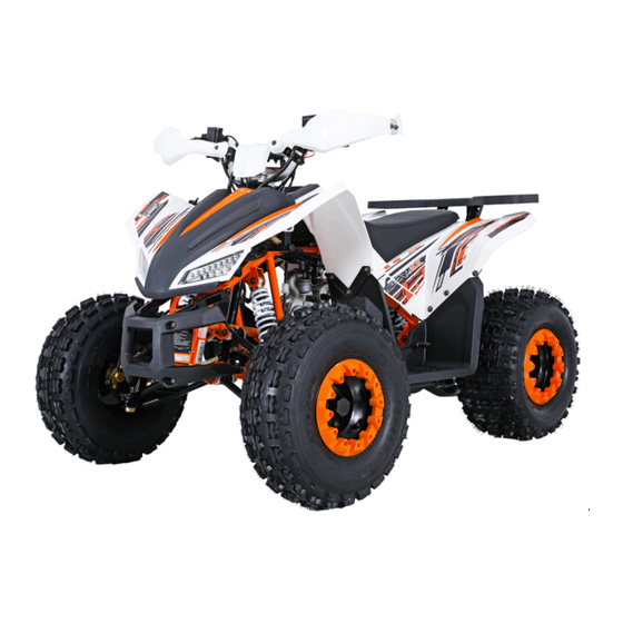
AT125EX
ASSEMBLY INSTRUCTIONS
PLEASE NOTE THAT THIS IS NOT THE OWNER'S MANUAL BUT THE
ASSEMBLY INSTRUCTIONS ONLY.
BEFORE OPERATING THIS ATV, MAKE SURE THE OPERATOR HAS
READ AND UNDERSTANDS THE OWNER'S MANUAL, WARNING
LABELS AND IS FAMILIAR WITH ALL OF THE ATV CONTROLS.
FOR QUESTIONS REGARDING THE ASSEMBLY OF THIS ATV PLEASE
CALL COLEMAN POWERSPORTS 888-405-8725
031218
Advertisement
Table of Contents

Subscribe to Our Youtube Channel
Related Manuals for Coleman Powersports AT125EX


Summary of Contents for Coleman Powersports AT125EX
-
Page 1: Rim Covers
ASSEMBLY INSTRUCTIONS ONLY. BEFORE OPERATING THIS ATV, MAKE SURE THE OPERATOR HAS READ AND UNDERSTANDS THE OWNER’S MANUAL, WARNING LABELS AND IS FAMILIAR WITH ALL OF THE ATV CONTROLS. FOR QUESTIONS REGARDING THE ASSEMBLY OF THIS ATV PLEASE CALL COLEMAN POWERSPORTS 888-405-8725... - Page 2 PARTS Owner’s Fuel Vent Tool Kit tube Manual Tie Rod Assembly M10 Castle nuts M3 cotter pins M10 Lock Washers Front Bumper Assembly M8 x 20 Bolts M8 Lock nuts Front Bumper Rear Carrier Assembly M8x25 Socket head bolts Rear Carrier Battery Assembly Battery (1) Battery Changer...
-
Page 3: Table Of Contents
PARTS Handlebar Assembly M10 Lock Washers M6x16 M10 x 30 bolts Top Console Bracket M10 Lock nuts Handlebar Protectors M10 Washers Handlebar clamp brackets Hand protector M8 nuts mounting supports (10) M8x16 Bolts (10) Tire Assembly Back tire (2) Front tire (2) Rim Covers (4) Hub Caps M8 Lock Nut (8) -
Page 4: Handlebar Clamp Brackets
HANDLEBAR ASSEMBLY Handlebar clamp brackets M10 Lock Washers M6x16 (2) Top Console Bracket M10 x 30 bolts M10 Lock nuts M10 Washers Handlebar clamp bracket Steering assembly bracket 1. Attach bottom clamp brackets to steering assembly bracket using M10 Top Console x 30 bolts, M10 Bracket lock washers and... -
Page 5: M8 Lock Nut
ODOMETER ASSEMBLY Speed-odometer Console Top Console Bracket Install the odometer assembly with 2 M6x16 bolts on the top console bracket M6x16 bolt... - Page 6 HANDLEBAR ASSEMBLY Right/Left Brake Lever Install Black green wires 1. Plug the black and green wires into the right and left brake assembles 2. Install the right and left brake assembles using the M6x20 bolts M6x20 bolts...
-
Page 7: M8X16 Bolts
HAND PROTECTOR ASSEMBLY Hand protector mounting supports Handlebar Protectors M8 nuts (10) M8x16 Bolts (10) M8x16 Bolt Hand protector mounting support 1. Attach hand protectors by placing the mounting M8x16 supports around the Bolt handlebar as shown in the last photo. Secure with M8x16 bolt and nut five times per handle bar Hand... - Page 8 TIE ROD INSTALLATION M10 Washers M10 Castle nuts M3 cotter pins Front spindle assembly Tie Rod 1. Attach tie rod to front spindle assembly on both sides of ATV 2. Secure tie rod using M10 washer and M10 castle nut. Tighten snug 3.
-
Page 9: M6X15 Allen Head Cap Bolts
RIM INSTALL Front tire (2) M6x15 Allen head cap bolts (12) Rim Covers (4) M6 Lock Nuts (12) Back tire (2) 1. Place rim cover on tire, matching up the holes of the rim to the holes of the tire 2. - Page 10 REAR WHEEL INSTALL M4 Cotter pins Large M16 Washers Back tires M16 Castle nuts M16 Lock Washer Rim Covers (2) Hub caps NOTE: Fill tires with 4 PSI of air before assembly. 1. Slide rear wheels on rear axle assembly. Make sure valve stem on tire faces out.
- Page 11 REAR WHEEL INSTALL 4. Install cotter pin and bend over ends. 5. Install hub caps...
- Page 12 FRONT WHEEL INSTALL Hub caps Front tires M8 Lock nuts M8 Washer NOTE: Fill tires with 4 PSI of air before assembly. 1. Install front wheels. Make sure valve stem faces out. 2. Attach wheel with M8 washer, followed by M8 lock nut.
- Page 13 FRONT BUMPER INSTALL M8 Lock nuts Front Bumper M8 x 20 Bolts M8x20 bolt 1. Install front bumper with M8 x 20 bolts and M8 lock nuts. M8x20 bolts M8x20 bolts...
- Page 14 REAR CARRIER INSTALL Rear Carrier head bolts M8x25 socket Rear of the Unit Rear Carrier Carrier bracket 1. Fix the rear carrier on the carrier bracket with bolt M8x25 and lock nut M8x25 bolt...
- Page 15 BATTERY INSTALLATION WARNING Battery electrolyte (sulfuric acid) is poisonous, electrolyte can cause severe burns if contacts skin. Avoid contact with skin, eyes or clothing. If sulfuric acid is swallowed or splashed in the eyes, treat immediately. Sulfuric acid in the eyes can cause blindness. Serious internal injuries or death can result if swallowed.
- Page 16 Charging the battery Note: Do not turn the charger on before attaching the charger clips to the battery terminals. The standard charging rate is 0.7A x Battery 5 -10 hours. Maximum charging rate is 3A x 1hour Changer 1. Attach the Charger to the battery WARNING terminals.
- Page 17 HAS ALL INFORMATION REQUIRED FOR SAFETY, ENGINE PREPARATION, PRE-RIDE INSPECTION AND STARTING INSTRUCTIONS. NEVER START THE ENGINE WITHOUT READING AND FULLY UNDERSTANDING THE OWNER’S MANUAL AND ALL WARNINGS. IF YOU DID NOT GET AN OWNER’S MANUAL WITH THIS ATV, PLEASE CALL COLEMAN POWERSPORTS AT 888-405-8725.
Need help?
Do you have a question about the AT125EX and is the answer not in the manual?
Questions and answers