
Related Manuals for Coleman Powersports AT125UT


Summary of Contents for Coleman Powersports AT125UT
- Page 1 AT125UT Owner’s Manual READ THIS MANUAL CAREFULLY! It contains important safety and service information.
- Page 2 ! WARNING Operating, servicing and maintaining a passenger vehicle or off-road vehicle can expose you to chemicals including engine exhaust , carbon monoxide, phthalates, and lead, which are known to the state of California to cause cancer and birth defects or other reproductive harm.
- Page 3 Please read carefully before operating this Vehicle! This vehicle should only be assembled and prepped by authorized Coleman Powersports Dealer or professional motorcycle mechanic. You should never to try to attempt assembly of this vehicle, it should be done by professionals.
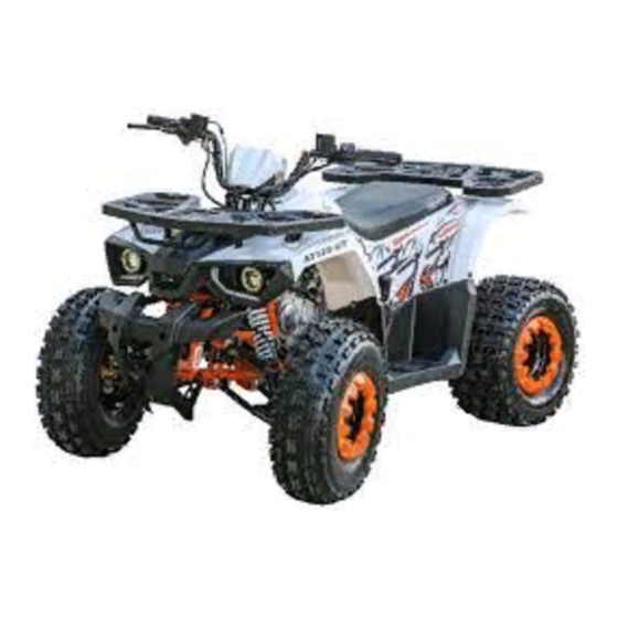
- Page 4 INTRODUCTION Thank you for purchasing the AT125UT. This ATV is designed for years of reliable use and family fun. This manual will provide you with a good basic understanding of the features and operation of this ATV. This manual includes important safety information. It also includes general riding techniques, maintenance and inspection procedures.
- Page 5 Product and specific tions are subject to change without notice. IMPORTANT NOTICE The AT125UT ATV is designed and manufactured for off-road use only. It is illegal and unsafe to operate this ATV on any public street, road or highway. This ATV complies with all applicable off-road noise level and spark arrester laws and NOTICE regulations.
- Page 6 Please read and understand all of the labels on your AT125UT ATV. These labels contain important information for safe and proper operation. Never remove any labels from your ATV. If a label becomes difficult to read or comes off, request a new replacement label from your Coleman Powersports dealer.
-
Page 7: Table Of Contents
Tires & Wear Limit ..................20 Electrical Wiring Diagram ................58 Chassis Fasteners ..................15 Electrical Connector Wiring Diagram ........... 59 Starting Engine ..................... 21 Coleman Powersports Limited Warranty ........60-62 Emission Control System Warranty ..........63-66 Engine Break-In ..................... 22... - Page 8 SAFETY INFORMATION THE AT125UT ATV IS NOT A TOY AND CAN BE HAZARDOUS TO OPERATE. MAKE SURE YOU UNDERSTAND ALL INSTRUCTIONS. PAY CLOSE ATTENTION TO THE WARNING AND CAUTION LABELS ON THE ATV. NEVER OPERATE THIS ATV WITHOUT PROPER TRAINING OR INSTRUCTION.
- Page 9 SAFETY INFORMATION Always avoid operating an ATV on any paved surfaces, including sidewalks, driveways, parking lots and streets. This ATV is designed for operation by a single person at least 10 years of age, without passengers. Never operate an ATV on any public street, road or highway, even a dirt or gravel road. This ATV is designed and manufactured for use only off public roads.
- Page 10 SAFETY INFORMATION (continued) Never permit anyone other than an adult to start the ATV. Drain gasoline from the fuel tank and carburetor prior to transporting the ATV. Caution the child and others near the vehicle not to get close to or touch any moving parts or any heated areas such as the engine and exhaust pipe.
-
Page 11: Engine Stop Lanyard Cord & Remote
ENGINE STOP LANYARD CORD & REMOTE The AT125UT has two emergency-stop engine switches. The primary emergency engine shut off switch is the lanyard cord and the secondary is the wireless engine shut off key fob. The wireless engine shut off key fob has a limited range that varies in different conditions DO NOT RELY solely on the key fob as the emergency engine shut off swich, especially during operator training. - Page 12 LANYARD CORD: The lanyard cord is designed for use by an adult supervising the child operating the ATV. When using the engine stop switch cord, be sure the speed limiter on the handlebar is adjusted and the engine speed limits the ATV to a walking speed.
-
Page 13: Transporting
TRANSPORTING THE ATV Avoid Carbon Monoxide Poisoning! All engine exhaust contains carbon monoxide, a deadly gas. Breathing carbon monoxide can cause headaches, dizziness, drowsiness, nausea, confusion, and eventually death. Carbon Monoxide is a colorless, odorless tasteless gas which may be present even if you do not see or smell any engine exhaust. Deadly levels of carbon monoxide can collect rapidly and you can quickly be overcome and unable to save yourself. -
Page 14: Description
DESCRIPTION Front Cargo Air Filter RIGHT SIDE LEFT SIDE Rack Rear Cargo Front Shock Battery Fuse 10 Amp Rack Fuel Cap Front Bumper Cover Muffler Foot Rest Gear Shifter Rear Shock Fuel On/Off Valve Spark Arrester Spark Plug Engine Oil Dip Stick... -
Page 15: Control Layout
CONTROL LAYOUT Parking Brake Speed Limiter Front Brake Lever Rear Brake Lever Start Button Throttle Lever Main Switch Lanyard Instrument Cluster Ignition OFF Ignition ON CONTROLS & FUNCTIONS IGNITION SWITCH The positions of the main switch are as follows. Ignition ON All electrical systems are supplied with power, and the engine can be started. The key cannot be removed. -
Page 16: Main Switch
Lanyard cap must be pushed in all the way for the engine to start. HEADLIGHTS This AT125UT ATV is equipped with High, Low, Strobe headlight features. When ignition key is set to the " On " potion press the headlight switch to turn on headlights and to toggle through modes. -
Page 17: Instrument Cluster
INSTRUMENT CLUSTER The Instrument cluster displays many important information about the ATV. Make sure the rider is familiar with all the information displayed before riding ATV. Instrument panel icons 1. Engine RPM (multiplied by 1000r / min), with the change in engine RPM display will also change. 2. -
Page 18: Speed Limiter
SPEED LIMITER The AT125UT ATV is equipped with a vehicle speed limiter adjusting screw. Beginning riders should start with slowest setting to learn how to control this vehicle. Once the operator has demonstrated mastery of the ATV, the supervising adult can adjust speed limiter screw to increase the top speed . The vehicle speed limiter keeps the throttle from fully opening, even when the throttle lever is pushed to the maximum. -
Page 19: Parking Brake
PARKING BRAKE Use the parking brake before starting the engine or after parking the ATV, especially on a slope. This ATV is equipped with dual parking brakes. Rear Axle Parking Brake: Apply the rear brake lever and push down the lock button to apply the parking brake. Squeeze the rear brake lever to release the parking brake. -
Page 20: Choke Lever
CHOKE LEVER Starting a cold engine requires a richer air-fuel mixture. Move the choke lever all the way up when starting a cold engine. Once the engine is warmed up return the choke lever all the way down in the running position. Choke Lever NOTICE For maximum engine life, never accelerate hard when the engine is cold or choke lever is in the... -
Page 21: Fuel Tank Capacity
FUEL TANK CAPACITY Gasoline and gasoline vapors are extremely flammable. To avoid fires, explosions and to reduce the risk of injury when refueling, follow these instructions. Before refueling, turn off the engine and be sure that no one is sitting on the vehicle. -
Page 22: Fuel Tank Cap
FUEL TANK CAP Remove the fuel tank cap by turning it counter clockwise. Turn the fuel tank cap fully clockwise to make sure it is securely closed Your ATV’s engine has been designed to use regular unleaded gasoline with a pump octane number of 91 or higher. -
Page 23: Fuel Cock/Fuel Valve
FUEL COCK/ FUEL VALVE FUEL COCK/ FUEL VALVE The fuel cock/valve supplies fuel from the tank to the carburetor. The fuel cock/valve lever positions are explained as follows and shown in the illustrations. FUEL OFF Arrow mark positioned over “OFF” position. Fuel is off and fuel will not flow to the carburetor. Always turn the fuel valve to the"‘OFF" position and allow the engine to idle until it burns remaining fuel in the line when the ATV is being stored. -
Page 24: Seat
SEAT To Remove Seat To remove the seat, pull the seat lock lever(#1) backward and then pull up the seat. The seat lock is located under the seat in the back of the ATV. To Install Seat Insert tab(#3) on the front of the seat into the seat holder(#2) and push down on the seat at the rear. Make sure that the seat is securely installed in place and will not move during operation. -
Page 25: Under Seat Compartment
NOTICE Positive (+) cable is red in color. Negative(-) Cable is in black in color. This AT125UT ATV has two positive (+) cables red in color. Both attach to positive terminal on the battery . Battery electrolyte is poisonous and dangerous, acid contains sulfuric acid, which can cause severe burns. Avoid contact with skin, eyes or clothing. -
Page 26: Battery Charging & Changing Fuse
3.Set ignition key to the "ON" position, to check if all the devices are operating. 4.Reinstall seat. If the fuse immediately blows, contact Coleman Powersports customer service. Always use a fuse of the specified rating, and never use substitute object in place of the proper fuse. -
Page 27: Pre-Ride Safety Checks
Failure to inspect or maintain the vehicle properly increases the possibility of an accident or equipment failure. Do not operate the vehicle if any problem is discovered. If a problem cannot be corrected by the procedures described in this manual, have the vehicle inspected by Coleman Powersports Customer Service ITEM ROUTINE... - Page 28 ITEM ROUTINE PAGE Throttle Lever • Make sure that operation is smooth. Lubricate cable and lever housing if necessary. • Check lever free play, and adjust if necessary. Control Cables • Make sure that operation is smooth. Lubricate if necessary. 5-10 Drive Chain •...
-
Page 29: Front & Rear Brakes
Check for correct free play in the brake levers. If the free play is incorrect, adjust it. Check operation of the levers. They should move smoothly and there should be a firm feeling when the brake is applied. If not, have the ATV checked by a Coleman Powersports Customer Service. -
Page 30: Tires & Wear Limit
TIRES Check tire pressure before each ride to make sure it is at the recommended specifications. Also check for wear and damage. Adjust tire pressures when the tires are cold. Tire pressure must be the same per axle. This ATV is equipped with tubeless tires with valves. -
Page 31: Chassis Fasteners
CHASSIS FASTENERS Make sure that all nuts, bolts and screws are properly tightened before starting engine. STARTING ENGINE (COLD) Set the parking brake. (The engine can be started only when the rear front/rear brake lever is applied.) Turn the fuel valve lever to the "ON" position. Turn the ignition key to the "ON"... -
Page 32: Engine Break-In
ENGINE BREAK-IN Proper engine break-in will increase the lifespan of your Coleman Powersports ATV. The engine break-in period is the initial 20 hours of operation. You should avoid maintaining a constant engine RPM and do not operate your ATV above 1/2 throttle during the break-in period. -
Page 33: Parking, Accessories & Modifications, Rear Cargo Rack
Use caution when adding electrical accessories. If electrical accessories exceed the capacity of the ATV’s electrical system, an electric failure could result, which could cause a dangerous loss of electrical system or engine power. Installing aftermarket parts and/or accessories could void your Coleman Powersports warranty. Call Coleman Powersports for details. -
Page 34: Gear Selector Lever
GEAR SELECTOR LEVER This ATV is equipped with a 2 gear transmission gearbox, The gear shift lever is located on the left side of the ATV. To change the transmission position completely stop vehicle, apply brakes then move the lever to the desired position. To Engage Forward Gear: Push forward on gear shifter lever. -
Page 35: Throttle Cable & Throttle Cable Adjustment
THROTTLLE CABLE ADJUSTMENT Check throttle lever free-play, adjust if necessary. NOTE If cable adjustment is unattainable, call Coleman Powersports Custom Service Normal throttle free-play is 5mm to 10mm 0.197 In to 0.394 Throttle cable lubrication Lubricate cable using silicone cable lubricant to reduce premature wear and to ensure proper movement of the cable. -
Page 36: Brakes
BRAKES Replacement of brake components requires professional knowledge. Brake service should be performed by an authorized Coleman Powersports service center. Operating with improperly adjusted brakes could lead to a loss in braking ability and an accident. The brakes can be very hot after prolong use of the vehicle and can cause burns. Wait for the brake to cool down. - Page 37 Brake fluid replacement or brake system maintenance and repairs should be performed by an authorized Coleman Powersports service center. NOTICE The brakes can be very hot after prolong use of the vehicle and can cause burns. Wait for the brake to cool down.
- Page 38 Have your local and authorized Coleman Powersports service center inspect brakes system for wear or damage. NOTICE If any problem is found concerning the brake system contact Coleman Powersports Customer Service for service . Recommended Brake Fluid Always use recommended brake fluid DOT 4 or 3.
-
Page 39: Engine Idle Adjustment
ENGINE IDLE ADJUSTMENT If the engine idle speed is not satisfactory, and all other conditions are favorable, the carburetor can be adjusted as follows: Place the transmission in neutral with the parking brake applied. Warm up the engine by running the vehicle. Adjust the carburetor idle screw until the desired idle RPM is reached. -
Page 40: Adjusting Suspension Spring Preload
ADJUSTING SUSPENSION SPRING PRELOAD This ATV is equipped with adjustable coil springs front and rear . The spring preload can be adjusted to suit the rider’s weight and the riding conditions. Turn the spring preload adjusting ring to increase (stiffest= 5) or decrease (softest= 1) the spring preload. -
Page 41: Maintenance
Due to the nature of the adjustments marked with a √ on the following chart, it is recommended CAUTION that service be performed by an authorized Coleman Powersports service center • Perform maintenance more often if you use your ATV under severe conditions, such as dirty or wet conditions to purge water or dirt contamination from grease fittings and other critical components. -
Page 42: Getting To Know Your Atv
GETTING TO KNOW YOUR ATV... - Page 43 If your child is a beginner or is inexperienced, he or she should take a training course, free of charge. The free training course is available to purchasers of new AT125UT by calling (855) 717-8618.
- Page 44 Never carry a passenger. Carrying a passenger on this ATV greatly reduces your ability to balance and control this ATV. You could have an accident, resulting in severe injury or death to you and/or your passenger. The long seat is to allow the operator to shift position as needed during operation.
- Page 45 Protective clothing Protective Goggles Protective Gloves Protective Boots Protective Helmet Do not operate after or while consuming alcohol or drugs. The operator’s performance capability is reduced by the influence of alcohol or drugs. Consuming alcohol or drugs could seriously affect your judgment, cause you to react more slowly, and affect your balance and perception.
- Page 46 DURING RIDING Always keep your feet on the foot boards during operation; otherwise, they may contact the rear wheels. Removing even one hand or foot can reduce your ability to control the ATV or could cause you to lose your balance and fall off of the ATV. If you remove a foot from a foot board, your foot or leg may come into contact with the rear wheels, which could injure you or cause an accident.
- Page 47 Never operate this ATV on any public street, road or highway, even a dirt or gravel one. You could collide with another vehicle. Know the terrain where you ride. Ride cautiously in unfamiliar areas. Stay alert for holes, rocks, or roots in the terrain, and other hidden hazards which may cause the ATV to upset.
- Page 48 Do not ride in areas posted “no trespassing. ” Do not ride on private property without getting permission. OPERATING YOUR COLEMAN POWERSPORTS ATV: Select a large, flat off-road area to become familiar with your ATV. Make sure that this area is free of obstacles and other riders.
- Page 49 STEERING YOUR ATV To achieve maximum traction while riding off road, the two rear wheels turn together at the same speed. Therefore, unless the wheel on the inside of the turn is allowed to slip or lose some traction, the ATV will resist turning. A special turning technique must be used to allow the ATV to make turns quickly and easily.
- Page 50 Avoid higher speeds until you are thoroughly familiar with the operation of your ATV. Do not attempt to climb hills until you have mastered basic maneuvers on fl t ground. Always check the terrain carefully before attempting any hill. In all cases avoid inclines with slippery or loose surfaces, or obstacles that might cause you to lose control.
- Page 51 Stalling, rolling backwards or improperly dismounting while climbing a hill could result in ATV overturning. If you cannot control the ATV, dismount immediately on the uphill side. DOWNHILL RIDING When riding your ATV downhill, shift your weight as far to the rear and uphill side of the ATV as possible.
- Page 52 WATER CROSSINGS The ATV can be used to cross slow moving, shallow water of up to a maximum of 11 cm (4 in) in depth. Before entering the water, choose your path carefully. Enter where there is no sharp drop off, and avoid rocks or other obstacles which may be slippery or upset the ATV.
-
Page 53: Specification Chart
SPECIFICATION CHART ENGINE Fuel Tank ..............58Gal (2.2L) Type ............... Single-Cylinder Four-Stroke, Engine Oil ............SAE 15W40 ................. Air-Cooled, Automatic ................. Centrifugal Clutch Climbing .............. ≥12° Displacement ..........120CC Acceleration Noise Level ........ ≤80dB Bore X Stroke ..........52.4 mm x 55.5 mm Recommended Tire Pressure ...... -
Page 54: Maintenance Chart
PERIODIC MAINTENANCE CHART FOR THE EMISSION CONTROL SYSTEM • For ATVs not equipped with an odometer or an hour meter, follow the month maintenance intervals. • For ATVs equipped with an odometer or an hour meter, follow the km (mi) or hours maintenance intervals. However, keep in mind that if the ATV isn’t used for a long period of time, the month maintenance intervals should be followed. - Page 55 GENERAL MAINTENANCE AND LUBRICATION CHART INITIAL EVERY WHICHEVER COMES FIRST Month CHECK OR km (mi) 1300 2500 2500 5000 MAINTENANCE JOB (200) (800) (1600) (1600) (3200) ITEM Hours Air Filter Element • Clean and replace if necessary. Every 20-40 hours (more often in wet or dusty areas) Front Brake* •...
- Page 56 GENERAL MAINTENANCE AND LUBRICATION CHART CONTINUED WHICHEVER COMES FIRST INITIAL EVERY Month CHECK OR km (mi) 1300 2500 2500 5000 MAINTENANCE JOB (200) (800) (1600) (1600) (3200) ITEM Hours Wheel Hub • Check for looseness or damage, and replace if necessary. ...
- Page 57 GENERAL MAINTENANCE AND LUBRICATION CHART CONTINUED WHICHEVER COMES FIRST INITIAL EVERY Month CHECK OR km (mi) 1300 2500 2500 5000 MAINTENANCE JOB (200) (800) (1600) (1600) (3200) ITEM Hours Moving Parts and • Lubricate Cables* • Check operation and correct if necessary. Throttle Lever ...
- Page 58 PERIODIC MAINTENANCE RECORD MAINTENANCE SERVICING DATE SERVICING DEALER OR PERSON REMARK INTERVAL PERFORMED...
-
Page 59: Engine Oil
ENGINE OIL The engine oil level should be checked before each ride. In addition, the oil must be changed at the intervals specified in the periodic maintenance and lubrication chart. Your new vehicles engine comes with shipping oil, shipping oil must be changed before the engine NOTE is started for the first time. - Page 60 To change the engine oil 1.Place the ATV on a level surface. 2.Place an oil pan under the engine to collect the used oil. 3.Remove the engine oil filler cap, and then remove the engine oil drain bolt to drain the oil from the crankcase.
-
Page 61: Cleaning Air Filter Element
CLEANING AIR FILTER ELEMENT The air filter element should be serviced at the intervals specified in the periodic maintenance and lubrication chart. Clean or, if necessary, replace the air filter element more frequently if you are riding in unusually wet or dusty areas. Never use low-flash-point solvents or gasoline to clean the air filter element because the engine could catch fire or explode. -
Page 62: Spark Plug
SPARK PLUG Checking the spark plug The spark plug is an important engine component, which is easy to check. The spark plug should be removed and checked in accordance with the periodic maintenance and lubrication chart. To remove the spark plug 1. -
Page 63: Drive Chain & Adjustment
DRIVE CHAIN Checking Drive Chain Slack The drive chain slack should be checked before each ride. To check the drive chain slack 1.Place the ATV on a level surface 2.Place the gear shifter to Neutral position 3.Move the ATV back and forth to locate the tightest portion of the drive chain, and then measure the drive chain slack as shown. 4.If the drive chain slack is incorrect, adjust chain before riding ATV. - Page 64 DRIVE CHAIN ADJUSMENT To adjust the drive chain slack 1.Loosen axle carrier/housing bolts. 2.On Models equipped with a chain tensioner, lift and hold the chain tension off the chain to release chain tension until the chain adjustment is completed. Carrier Housing Bolts...
- Page 65 To tighten drive chain, 1.Loosen the chain adjuster nut(#1) on the back side of the carrier/housing tap. 2.Tighten the chain adjuster nuts(#2) to move the carrier/housing forward. 3.When proper chain slack is achieved tighten chain adjuster nuts (#1,3). To loosen drive chain, 1.Loosen the chain adjuster nut(#1) on the back side of the carrier/housing tap.
-
Page 66: Lubricating Pivoting Joints
Extreme pressure and water resistant grease is recommended. This AT125UT has multipliable grease nipples located in front and rear pivoting arms and on the steering shaft. For Lubricating grease nipple, use an automotive grease gun. -
Page 67: Cleaning Spark Arrester
CLEANING SPARK ARRESTER Be sure the exhaust pipe and muffler are cool before cleaning the spark arrester. 1.Unscrew the 3(8mm) bolts (#4) securing the muffler end cap to muffler by using a 8mm socket wrench. 2.Unscrew the 3 Phillips screws (#5) securing spark arrester to muffler. 3.Carefully remove the spark arrester from the muffler assembly. -
Page 70: Coleman Powersports Limited Warranty
The Product is warranted to be free from manufacturing defects in material and workmanship for a period of 90 days from the date of purchase shown on the sales receipt. During this period of time Coleman Powersports will, at its option, either repair or replace any original Coleman Powersports part which is covered by this warranty and is proven to be defective in workmanship or material. - Page 71 The retailer of this product does not make any warranty of its own and has no authority to implement this warranty on behalf of Coleman Powersports without the approval of Coleman Powersports. A COPY OF YOUR SALES RECEIPT IS REQUIRED FOR WARRANTY SERVICE.
- Page 72 Other loss or damage to other equipment or personal items. Length of Implied Warranties: Any implied warranties are limited to the duration set forth in this warranty. Coleman Powersports does not make any claim as to the merchantability or fitness for a particular purpose which would extend longer than the duration of this written warranty.
-
Page 73: Emission Control System Warranty
Where a warrantable condition exists, Coleman Powersports will repair your vehicle at no cost to you, including diagnosis, parts and labor. If an emission-related part on your vehicle is defective, the part will be repaired or replaced by Coleman Powersports. This is your emission control system defects warranty. - Page 74 30 days. As the vehicle owner, you should be aware that Coleman Powersports may deny your warranty coverage if your vehicle or a part has failed due to abuse, neglect, improper maintenance or unapproved modifictions.
- Page 75 Coleman Powersport’s dealer. Coleman Powersports shall not be liable for any other expenses, loss or damage, whether direct, incidental, consequential or exemplary arising in connection with the sale or use of or inability to use the vehicle for any purpose.
- Page 76 B. No express emission control system warranty is given by us except as specifically set orth herein. Any emission control system warranty implied by law,including any warranty of merchantability or fitness or a particular purpose, is limited to the express emission control system warranty terms stated in this warranty.
- Page 77 POWERSPORTS...
- Page 78 Find important product information and how-to videos on our website www.taomotor.com...
Need help?
Do you have a question about the AT125UT and is the answer not in the manual?
Questions and answers
i am looking for a reset for the quad one of the saftey wires came off the break i put it on and still no spark
To reset the Coleman Powersports AT125UT after a safety wire came off the brake and there is no spark, follow these steps:
1. Check the safety wire: Reattach the safety wire to the brake properly. Ensure it is securely connected and the brake system is functioning.
2. Inspect the ignition system:
- Check the spark plug for damage, wear, or carbon buildup. Clean or replace it if needed.
- Measure the spark plug gap and adjust it to 0.06–0.085 mm (0.024–0.028 in) if necessary.
- Make sure the spark plug cap, coil wire, and ignition coil are properly connected.
3. Check the engine stop switches:
- Make sure the lanyard cord is properly attached.
- Ensure the wireless key fob is within range and functioning. Replace its battery if needed.
- Confirm the ignition switch is in the ON position.
4. Try starting the engine:
- Set the main switch to ON.
- Make sure the gear shifter is in Neutral.
- Press the start button to crank the engine.
If there is still no spark, inspect all electrical connections and consider checking the fuse (10 Amp) or consulting a technician.
This answer is automatically generated
Color of wires are different