Rigol RSA5000 Series User Manual
Real-time spectrum analyzer
Hide thumbs
Also See for RSA5000 Series:
- Programming manual (268 pages) ,
- Performance verification manual (43 pages) ,
- User manual (206 pages)

Related Manuals for Rigol RSA5000 Series


Summary of Contents for Rigol RSA5000 Series
- Page 1 RIGOL User’s Guide RSA5000 Series Real- time Spectrum Analyzer Dec. 22, 2017 RIGOL TECHNOLOGI ES, I NC. www.valuetronics.com...
- Page 2 www.valuetronics.com...
- Page 3 China as well as the I SO9001:2008 standard and the I SO14001:2004 standard. Other international standard conformance certif ications are in progress. Contact Us I f you have any problem or requirement when using our products or this manual, please contact RIGOL E-mail: service@rigol.com Website: www.rigol.com RSA5000 User's Guide www.valuetronics.com...
-
Page 4: Safety Requirement
RIGOL Safety Requirement General Safety Summary Please review the following safety precautions carefully before putting the instrument into operation so as to avoid any personal injury or damage to the instrument and any product connected to it. To prevent potential hazards, please follow the instructions specif ied in this manual to use the instrument properly. - Page 5 RIGOL Avoid Circuit or Wire Exposure. Do not touch exposed junctions and components when the unit is powered on. Do Not Operate With Suspected Failures. I f you suspect that any damage may occur to the instrument, have it inspected by RIGOL authorized personnel before further operations.
-
Page 6: Safety Notices And Symbols
RIGOL Safety Notices and Symbols Safety Notices in this Manual: WARNI NG I ndicates a potentially hazardous situation or practice which, if not avoided, will result in serious injury or death. CAUTI ON I ndicates a potentially hazardous situation or practice which, if not avoided, could result in damage to the product or loss of important data. -
Page 7: Care And Cleaning
RIGOL Care and Cleaning Care Do not store or leave the instrument where it may be exposed to direct sunlight for long periods of time. Cleaning Clean the instrument regularly according to its operating conditions. Disconnect the instrument from all power sources. -
Page 8: Rsa5000 Series Overview
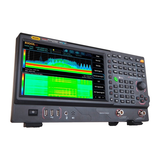
With superb performance specif ications and the clear user interface, the RSA5000 series allows you to operate it through various ways, such as pressing keys on the front panel, using the touch screen, connecting the mouse and the keyboard. -
Page 9: Document Overview
RIGOL Document Overview Topics in this manual: Chapter 1 Quick Start This chapter introduces the front/ rear panel and user interface as well as announcements during f irst use of the analyzer. Chapter 2 Functions of the Front Panel of GPSA This chapter gives detailed function descriptions of the GPSA's front panel keys and the associated menu keys. - Page 10 Center Freq Content Conventions in this Manual: The RSA5000 series spectrum analyzer includes the following models. This manual takes RSA5065-TG as an example. Model Frequency Range Tracking Generator RSA5065 9 kHz to 6.5 GHz...
-
Page 11: Table Of Contents
General Safety Summary ................I I Safety Notices and Symbols ..............I V Care and Cleaning ..................V Environmental Considerations ..............V RSA5000 Series Overview ..............VI Document Overview ................VI I Chapter 1 Quick Start ................. 1-1 General I nspection ................1-2 Appearance and Dimensions .............. - Page 12 RIGOL Contents AMPT ..................... 2-9 Sweep and Function Settings..............2-14 BW ....................2-14 Sweep ..................2-18 Trigger ..................2-22 Trace .................... 2-26 Tracking Generator (Option) ............2-32 Measurement Settings ................2-35 Meas .................... 2-35 Meas Setup ................... 2-38 Marker Measurement ................2-66 Marker ..................
- Page 13 Contents RIGOL Recall ................... 6-13 Save ..................... 6-15 Chapter 7 Remote Control ..............7-1 Remote Control Overview ............... 7-2 Remote Control via USB ................. 7-3 Remote Control via LAN ................. 7-4 Chapter 8 Troubleshooting ..............8-1 Chapter 9 Appendix ................9-1 Appendix A: RSA5000 Accessories and Option List ........
- Page 14 www.valuetronics.com...
-
Page 15: Chapter 1 Quick Start
Chapter 1 Quick Start This chapter gives you a quick review about the appearance and dimensions of the RSA5000 series, its front and rear panel, user interface, as well as announcements during f irst use of the analyzer. Contents in this chapter: ... -
Page 16: General I Nspection
RIGOL Chapter 1 Quick Start General I nspection 1. I nspect the packaging I f the packaging has been damaged, do not dispose the damaged packaging or cushioning materials until the shipment has been checked for completeness and has passed both electrical and mechanical tests. -
Page 17: Appearance And Dimensions
Chapter 1 Quick Start RIGOL Appearance and Dimensions Figure 1-1 Front View Unit: mm Figure 1-2 Vertical View Unit: mm RSA5000 User's Guide www.valuetronics.com... -
Page 18: To Prepare For Use
RIGOL Chapter 1 Quick Start To Prepare for Use To Adjust the Supporting Legs You can unfold the supporting legs to use them as stands to tilt the instrument upwards for easier operation and observation. You can also fold the supporting legs for easier storage or shipment when the instrument is not in use. -
Page 19: To Connect To Ac Power
Chapter 1 Quick Start RIGOL To Connect to AC Pow er Please use the power cord provided in the accessories to connect the spectrum analyzer to the AC power source. The AC power supply specif ication of this spectrum analyzer is 100-240 V, 45-440 Hz. The power consumption of the instrument cannot exceed 95 W. -
Page 20: To Set The System Language
RIGOL Chapter 1 Quick Start To Set the System Language RSA5000 series spectrum analyzer supports multiple system languages. You can System Language press to switch the system language. RSA5000 User’s Guide www.valuetronics.com... -
Page 21: Front Panel
Chapter 1 Quick Start RIGOL Front Panel The front panel of RSA5000 is shown in the following f igure. 14 13 12 11 10 Figure 1-4 Front Panel Table 1-1 Front Panel Description Description Description Numeric keypad [ 1] Menu softkeys... -
Page 22: Function Keys On The Front Panel
RIGOL Chapter 1 Quick Start Function Keys on the Front Panel Figure 1-5 Function Keys Table 1-2 Descriptions of Function Keys on the Front Panel Function Key Description Sets the parameters such as center frequency, start frequency, and stop frequency; enables the signal tracking function. - Page 23 Chapter 1 Quick Start RIGOL Sets other system parameters based on the current marker value. I ndicates the special functions of the marker, such as noise marker, N dB bandwidth measurement, and frequency counter. Sets the sweep parameters. Sets the sweep/ measurement mode to be continuous.
-
Page 24: Utility Function Keys On The Front Panel
RIGOL Chapter 1 Quick Start Tip: Click the function keypad icon at the right corner of the LCD or f inger-touch it, and then the function keypad that corresponds to the specif ied keys on the front panel appears. At this time, you can operate the instrument with the function keypad. -
Page 25: Front Panel Key Backlight
Chapter 1 Quick Start RIGOL Front Panel Key Backlight The on/ off state and the color of the backlights of some keys on the front panel indicate the working state of the spectrum analyzer. The states are listed below. Pow er Key ... -
Page 26: Front Panel Connector
RIGOL Chapter 1 Quick Start Front Panel Connector USB HOST Earphone Jack RF I nput TG Output Figure 1-6 Front Panel Connector USB HOST The analyzer can serve as a "master" device to connect to the external USB device. The USB storage device, mouse, and keyboard can be connected to the instrument via the interface. - Page 27 Chapter 1 Quick Start RIGOL Earphone Jack I nsert the earphone to the jack to acquire the audio output of the demodulated signal. CAUTI ON To avoid damaging your hearing, please turn the volume down to zero f irst and then gradually turn the volume up after putting on the earphone.
-
Page 28: To Use The Numeric Keypad
RIGOL Chapter 1 Quick Start To Use the Numeric Keypad The numeric keypad is available on the front panel of RSA5000, as shown in the f igure below. The numeric keypad supports the Chinese characters, English uppercase/ lowercase letters, numbers, and common symbols (including decimal... - Page 29 Chapter 1 Quick Start RIGOL The number input mode is, by default, selected for parameter setting. Press this key to input the symbol ("+ " or "-"). When you press the key for the f irst time, the parameter symbol "-" is displayed, and when you press it again, "+ "...
-
Page 30: Rear Panel
RIGOL Chapter 1 Quick Start Rear Panel The rear panel of RSA5000 is shown in the following f igure. Figure 1-8 Rear Panel AC Pow er Cord Connector The AC power supply specif ication of RSA5000 is: 100-240 V; 45-440 Hz. - Page 31 The analyzer can serve as a "slave" device to connect to the external USB device. The analyzer can be connected to the PC through this interface. Then, the RSA5000 series spectrum analyzer can be controlled remotely through programming or the PC software.
-
Page 32: User I Nterface
RIGOL Chapter 1 Quick Start 13. I F OUT I ndicates the intermediate frequency signal in the output RF component. I ts center frequency is 430 MHz. User I nterface 11 12 23 22 17 16 Figure 1-9 User I nterface... - Page 33 Chapter 1 Quick Start RIGOL [ 1] Trace indicator Displays information about the trace and the detector. I nformation setting : indicates messages, such as the prompt messages, alarm messages, and error messages. : indicates the speaker. You can tune it up and...
-
Page 34: Mouse/ Keyboard/ Touch Screen Operation Rule
RIGOL Chapter 1 Quick Start frequency and stop frequency. Y scale I ndicates the scale indication in the Y axis. [ 1] Note The display of the trace indicator is shown in the following f igure: Trace Number Trace Type Detector Type ... -
Page 35: Keyboard Operation Rule
Chapter 1 Quick Start RIGOL Keyboard Operation Rule Connect the keyboard to the spectrum analyzer via the USB HOST interface, and then use the shortcut keys on the keyboard to perform the same function as what you do with the front panel keys. -
Page 36: Touch Screen Operation Rule
RIGOL Chapter 1 Quick Start numbers (1, 2, 3, 4, 5, 6, 7, 8, 9, 0) and a decimal point(.) Back Backspace Enter Enter ↑ ↓ ← → Arrow keys (Up/ Down/ Left/ Right arrow key) 7 menu softkeys from top to... -
Page 37: Menu Operation
Chapter 1 Quick Start RIGOL Menu Operation There are 6 types of menus according to their operation modes. Each type of menu and its operation method are introduced below. Parameter I nput Select the menu and use the numeric keys to modify the value directly. - Page 38 RIGOL Chapter 1 Quick Start Tip: The above menu operations can be executed by touch gestures or clicking with the externally connected mouse. Also, you can connect to the keyboard and use the shortcut keys to perform the above menu operations. For the matching relations between the front panel keys and the keyboard shortcut keys, refer to Table 1-5.
-
Page 39: Parameter Setting
Chapter 1 Quick Start RIGOL Parameter Setting You can enter the desired parameter values by using the numeric keys, the knob, or arrow keys on the front panel. Also, you can set the parameters by using the touch screen, the externally connected keypad or the mouse. This section takes an example (set the center frequency to 800 MHz) to describe six methods of parameter setting. - Page 40 RIGOL Chapter 1 Quick Start Then the numeric keypad is displayed. I nput 800, and select the desired unit "MHz". Use the keyboard Press "Shift + f " to open the Frequency menu; Center Freq Press "F1" to select I nput 800 by using the numeric keys;...
-
Page 41: To Use The Built-In Help System
Chapter 1 Quick Start RIGOL To Use the Built-in Help System The built-in help system provides information about every function key on the front panel and every menu softkey. Get the built-in help information Help Press and a prompt message about how to obtain help information will be shown on the screen. -
Page 42: Fuse Replacement
RIGOL Chapter 1 Quick Start Fuse Replacement I f you need to replace the fuse, use only the specif ied fuse (AC 250V, T3.15A) and perform the following operations: . Turn off the instrument, cut off the power, and remove the power cord. -
Page 43: Mode Setting
Chapter 1 Quick Start RIGOL Mode Setting Mode Provides two working modes: GPSA (general purpose spectrum analyzer) and RTSA (real-time spectrum analyzer). Note: I n different working modes, the functions of the keys on the front panel may Help be different. Press to display the help information of the current working mode. -
Page 44: Mode Setup
RIGOL Chapter 1 Quick Start Mode Setup The Mode Setup menu is used to set parameters global to different measurements under all working modes. These parameters are independent of the currently running measurement, and they are global to all the measurements. -
Page 45: Chapter 2 Functions Of The Front Panel Of Gpsa
Chapter 2 Functions of the Front Panel of GPSA RIGOL Chapter 2 Functions of the Front Panel of GPSA This chapter describes in detail the function keys on the front panel and their associated menu functions. Contents in this chapter: ... -
Page 46: Basic Settings
RIGOL Chapter 2 Functions of the Front Panel of GPSA Basic Settings FREQ Sets the frequency parameters of the analyzer. The analyzer sweeps within a specif ied frequency range and restarts sweeping every time the frequency parameters are modif ied. - Page 47 Chapter 2 Functions of the Front Panel of GPSA RIGOL Center Freq Sets the center frequency (that corresponds to the horizontal center of the graticule) of the current channel. Press this key or touch the specif ied menu item on the screen to set the frequency entry mode to Center Frequency/ Span.
- Page 48 RIGOL Chapter 2 Functions of the Front Panel of GPSA Start Freq Sets the start frequency of the current frequency channel. Press this key or touch the specif ied menu item on the screen to set the frequency entry mode to Start Frequency/ Stop Frequency.
- Page 49 Chapter 2 Functions of the Front Panel of GPSA RIGOL Parameter Setting refer to descriptions in " ". Table 2-3 Stop Frequency Parameter Remarks Default center frequency+ span/ 2 [ 1] Range 0 Hz to Fmax Unit GHz, MHz, kHz, Hz Knob Step span >...
- Page 50 RIGOL Chapter 2 Functions of the Front Panel of GPSA CF Step Mode The CF step mode consists of "Manual" and "Auto". Remarks: I n Auto mode, the CF step is 1/ 10 of the span in non-zero span mode or equals to RBW while in zero span mode.
- Page 51 Chapter 2 Functions of the Front Panel of GPSA RIGOL Start Execute a sweep Active Marker exists? Search for and mark the Search for frequency point (variation peak and < 3dB ) near the Marker mark it as Marker Set marker...
-
Page 52: Span
RIGOL Chapter 2 Functions of the Front Panel of GPSA SPAN Sets the span of the analyzer. Changing this parameter will change the frequency parameters, and after the span is changed, the sweep restarts. Span Sets the frequency range of the current channel. Press this key or touch the specif ied menu item on the screen to set the frequency entry mode to Center Frequency/ Span. -
Page 53: Ampt
Chapter 2 Functions of the Front Panel of GPSA RIGOL Full Span Sets the maximum span. Zero Span Sets the span to 0 Hz. The values of start frequency and stop frequency are the same as that of the center frequency. The X-axis is time. The analyzer measures the time-domain characteristics of the amplitude at the center frequency point of the input signal. - Page 54 RIGOL Chapter 2 Functions of the Front Panel of GPSA Table 2-7 Reference Level Parameter Remarks Default 0 dBm Range -170 dBm to 30 dBm Unit dBm, -dBm, V, mV, uV Knob Step I n Log scale mode, step = scale/ 10 Left/ Right Arrow Key Step I n Lin scale mode, step = 0.1 dBm...
- Page 55 Chapter 2 Functions of the Front Panel of GPSA RIGOL Atten Auto Selects "Manual" or "Auto" to be the current attenuation mode. Remarks: Attenuation To select "Manual" to be the attenuation mode, press to set the attenuation value, and the attenuation mode will be automatically switched to "Manual".
- Page 56 RIGOL Chapter 2 Functions of the Front Panel of GPSA Scale Type Sets the scale type of the Y-axis to Lin or Log. By default, it is Log. Remarks: I n Log scale type, the Y-axis denotes the logarithmic coordinate. The top line of the graticule is the reference level, and the scale per division represents the scale value.
- Page 57 Chapter 2 Functions of the Front Panel of GPSA RIGOL Max Mixer Lvl Sets the maximum input level of the mixer according to the amplitude of the signal. Remarks: For the high-level input signal, select a smaller maximum mixer level to increase the input attenuation and reduce the distortion of the signal;...
-
Page 58: Sweep And Function Settings
RIGOL Chapter 2 Functions of the Front Panel of GPSA Sw eep and Function Settings Sets the parameters such as RBW (Resolution Bandwidth) and VBW (Video Bandwidth). Sets the resolution bandwidth (RBW) to distinguish two signals whose frequencies are close with each other. - Page 59 Chapter 2 Functions of the Front Panel of GPSA RIGOL SPAN/ RBW Ratio Sets the ratio of span to RBW. You can use the numeric keys, the knob, and the arrow keys on the front panel to modify this parameter; also you can modify it on the Parameter Setting touchscreen.
- Page 60 RIGOL Chapter 2 Functions of the Front Panel of GPSA Sets the video bandwidth (VBW) to f ilter out the noises outside the video band. Remarks: Reducing VBW makes the spectral line smoother, so that the low-level signal in the noise can be detected, but this will also prolong the sweep time (when sweep time is set to Auto, it will be affected by both RBW and VBW).
- Page 61 Chapter 2 Functions of the Front Panel of GPSA RIGOL Table 2-15 VBW/ RBW Ratio Parameter Remarks Default Range 0.00001 to 3,000,000 Unit None Knob Step at 1-3-10 step Left/ Right Arrow Key Step Up/ Dow n Arrow Key Step...
-
Page 62: Sweep
RIGOL Chapter 2 Functions of the Front Panel of GPSA Sw eep Sets sweep-related parameters, such as sweep time, sweep points, and sweep mode. Sw eep Points Sets the number of points acquired in each sweep, i.g. the number of the trace points. - Page 63 Chapter 2 Functions of the Front Panel of GPSA RIGOL Table 2-17 Sweep Time Parameter Remarks Default 1 ms μs [ 1] Range to 6,000 s μs Unit s, ms, , ns, ps Knob Step μs sweep time/ 100, Min = 1...
- Page 64 RIGOL Chapter 2 Functions of the Front Panel of GPSA enabled, press this key to enter continuous sweep mode. I n this case, if the trigger conditions are met, the instrument will sweep continuously. I n continuous sweep mode, the system will send a trigger initialization signal automatically and enter the trigger condition judgment directly after each sweep is completed.
- Page 65 Chapter 2 Functions of the Front Panel of GPSA RIGOL ":I NI T" command through the remote interface) should be executed before judging the trigger conditions. Press “Single” Measurement status? Single sweep mode? Single sweep mode? Enter single sweep mode...
-
Page 66: Trigger
RIGOL Chapter 2 Functions of the Front Panel of GPSA Trigger Selects the trigger source and sets trigger-related parameters. Trigger Source Sets "Free Run", "External 1", "External 2", or "Video" to be the trigger source. Free Run The trigger conditions are met at any time, that is, the analyzer generates trigger signals continuously. - Page 67 Chapter 2 Functions of the Front Panel of GPSA RIGOL Trig Delay Sets the time interval during which the instrument waits to start the sweep operation after the trigger signal that meets the trigger conditions is generated. You can use the numeric keys, the knob, and the arrow keys on the front panel to modify this parameter;...
- Page 68 RIGOL Chapter 2 Functions of the Front Panel of GPSA Trigger Holdoff Sets the holdoff time between trigger signals. You can use the numeric keys, the knob, and the arrow keys on the front panel to modify this parameter; also you can Parameter modify it on the touchscreen.
- Page 69 Chapter 2 Functions of the Front Panel of GPSA RIGOL triggers on the rising edge … … trigger s ignal … … sweep measu rement1 trigger d elay aut o trig trigger d elay trigger occurs trigger occurs … …...
-
Page 70: Trace
RIGOL Chapter 2 Functions of the Front Panel of GPSA Trace Trace Displays the sweep signal on the screen. Press to set parameters for trace. Trace Selection RSA5000 can display at most 6 traces synchronously. Each trace is indicated in... - Page 71 Chapter 2 Functions of the Front Panel of GPSA RIGOL Detector Type Sets the detector for the current measurement. The selected detector can be applied to the selected trace. The available trace detectors include Pos Peak, Neg Peak, Normal, Sample, Average (RMS), and Average (Vol).
- Page 72 RIGOL Chapter 2 Functions of the Front Panel of GPSA ∑ × (2-9) Wherein, is the average of voltage in V; is the number of sampled values for each point displayed; and is the envelop of the sampled value in V.
- Page 73 Chapter 2 Functions of the Front Panel of GPSA RIGOL Load the stored data to trace. Trace data are cleared by the trace clear function. When inactive trace is displayed, the trace will not be zoomed in or out based on the setting of X-axis, but will move up and down based on the changes of Y-axis values.
- Page 74 RIGOL Chapter 2 Functions of the Front Panel of GPSA − (2-13) Trace Offset result I n the above formula, the parameter unit is dB. Op1–Op2+ Ref Operand 1 (Op1) minus Operand 2 (Op2), and then plus the reference (Reference). Then, saves the result to the destination trace. During the sweep,...
- Page 75 Chapter 2 Functions of the Front Panel of GPSA RIGOL Table 2-22 Offset Parameter Remarks Default 0 dB Range -100 dB to 100 dB Unit Knob Step 1 dB Left/ Right Arrow Key Step Up/ Dow n Arrow Key Step...
-
Page 76: Tracking Generator (Option)
RIGOL Chapter 2 Functions of the Front Panel of GPSA Tracking Generator ( Option) Sets the parameter related to the tracking generator (TG). This function is only available for RSA5065-TG/ RSA5032-TG. Tracking Generator Enables or disables the tracking generator. When the tracking generator is enabled, a signal with the same frequency as that of [ GEN OUTPUT 50Ω]... - Page 77 Chapter 2 Functions of the Front Panel of GPSA RIGOL Table 2-25 Tracking Generator Output Amplitude Offset Parameter Remarks Default 0 dB Range -200 dB to 200 dB Unit Knob Step 1 dB Left/ Right Arrow Key Step Up/ Dow n Arrow Key Step...
- Page 78 RIGOL Chapter 2 Functions of the Front Panel of GPSA Reference Position After the normalize function is enabled, you can adjust the vertical position of Reference Level on the screen by adjusting the reference position. The function of this menu is similar to that of Reference Level. When it is set to 0% , Reference Level is displayed at the bottom of the graticule and at the top line of the graticule when it is set to 100% .
-
Page 79: Measurement Settings
Chapter 2 Functions of the Front Panel of GPSA RIGOL Measurement Settings Meas Provides swept SA and VSWR, as well as multiple advanced measurement functions, including time-domain power, adjacent channel power, multi-channel power, occupied bandwidth, emission bandwidth, C/ N ratio, harmonics, and TOI . - Page 80 RIGOL Chapter 2 Functions of the Front Panel of GPSA resolution bandwidth of the analyzer will be adjusted to smaller values automatically. Multichan Pw r Meas Setup Select and then press to set the corresponding parameters. Occupied BW I ntegrates the power within the whole span and then calculates the bandwidth occupied by this power according to the specif ied power ratio.
- Page 81 Chapter 2 Functions of the Front Panel of GPSA RIGOL VSWR Enables or disables the VSWR measurement function. When the VSWR measurement function is enabled, the user interface is divided into two sections automatically (the lower section provides the measurement wizard). At this time, you can perform the Meas Setup VSWR measurement according to the wizard.
-
Page 82: Meas Setup
RIGOL Chapter 2 Functions of the Front Panel of GPSA Meas Setup Meas Open the parameter setting menu of the function selected in the menu. Sw ept SA Avg Number Specif ies the number of counts (N) for Average, Max Hold, and Min Hold. For Average, the greater the value of N, the smoother the trace is displayed. - Page 83 Chapter 2 Functions of the Front Panel of GPSA RIGOL OldAvg Newdata − × ( ) NewAvg 20log (2-17) I n the above formula, the parameter unit is dB. Avg State Enables or disables the auto average function. When the auto average function is enabled, the instrument will select the best average type based on the current settings.
- Page 84 RIGOL Chapter 2 Functions of the Front Panel of GPSA current editing point changes along with the center frequency. Y To Ref : When "Fixed" is selected, the amplitude of the current editing point will not be affected by the reference level. When "Relative"...
- Page 85 Chapter 2 Functions of the Front Panel of GPSA RIGOL 7) Deletes All Limits Deletes all limit lines. After you press the menu, the data of all the limit lines will be cleared and they will be restored to factory defaults.
- Page 86 RIGOL Chapter 2 Functions of the Front Panel of GPSA Time-domain Pow er ( T-Pow er) Measurement I nterface: Start Line Stop Line Measurement Result Measurement Parameters Figure 2-5 T-Power Measurement I nterface Measurement Result: T-power, i.g. the power of the signal from the start line to stop line.
- Page 87 Chapter 2 Functions of the Front Panel of GPSA RIGOL Avg Mode Sets the average mode to "Exponential" or "Repeat". The default average mode is "Exponential". When "Exponential" is selected, the result is the exponential average of the measurement results obtained in the past N times (N is specif ied in "...
- Page 88 RIGOL Chapter 2 Functions of the Front Panel of GPSA You can use the numeric keys, the knob, or arrow keys to modify this parameter; you can also use the touch screen to modify the parameter. Table 2-31 Stop Line for T-Power Measurement...
- Page 89 Chapter 2 Functions of the Front Panel of GPSA RIGOL Measurement I nterface: Main Channel Bandwidth Channel Spacing Adjacent Channel Bandwidth Figure 2-6 Adjacent Channel Power Measurement I nterface Measurement Results: main channel power, upper-adjacent channel power, and lower-adjacent channel power.
- Page 90 RIGOL Chapter 2 Functions of the Front Panel of GPSA Table 2-32 Average Count of ACP Measurement Parameter Remarks Default Range 1 to 1,000 Unit None Knob Step Left/ Right Arrow Key Step Up/ Dow n Arrow Key Step Avg Mode Sets the average mode to "Exponential"...
- Page 91 Chapter 2 Functions of the Front Panel of GPSA RIGOL Table 2-34 Adjacent Channel Bandwidth for ACP Measurement Parameter Remarks Default 2 MHz Range 33 Hz to 2.5 GHz Unit GHz, MHz, kHz, Hz Knob Step adjacent channel bandwidth/ 100,...
- Page 92 RIGOL Chapter 2 Functions of the Front Panel of GPSA Multichan Pw r Measurement I nterface: Channel Span Channel Span Channel Span Span Figure 2-7 Multi-channel Power Measurement I nterface Measurement Results: channel power and power spectral density Channel Power: power within the channel span.
- Page 93 Chapter 2 Functions of the Front Panel of GPSA RIGOL Avg Mode Sets the average mode to "Exponential" or "Repeat". The default average mode is "Exponential". When "Exponential" is selected, the result is the exponential average of the measurement results obtained in the past N times (N is specif ied in "...
- Page 94 RIGOL Chapter 2 Functions of the Front Panel of GPSA the span of the channel according to your needs, and then press Channel to add a channel. Table 2-37 Channel Span Parameter Remarks Default 3 GHz 10 Hz to 2* Min[ (channel –...
- Page 95 Chapter 2 Functions of the Front Panel of GPSA RIGOL Occupied BW Measurement I nterface: Figure 2-8 OBW Measurement I nterface Measurement Results : occupied bandwidth and transmit frequency error. OBW: Use the integral calculation method to calculate the power within the whole span, and then calculate the bandwidth occupied by the power based on the specif ied power ratio.
- Page 96 RIGOL Chapter 2 Functions of the Front Panel of GPSA Table 2-38 Average Count for OBW Measurement Parameter Remarks Default Range 1 to 1000 Unit None Knob Step Left/ Right Arrow Key Step Up/ Dow n Arrow Key Step Avg Mode Sets the average mode to "Exponential"...
- Page 97 Chapter 2 Functions of the Front Panel of GPSA RIGOL Table 2-39 Span for OBW Measurement Parameter Remarks Default 2 MHz Range 10 Hz to 6.5 GHz Unit GHz, MHz, kHz, Hz Knob Step OBW span/ 100, Min = 1 Hz...
- Page 98 RIGOL Chapter 2 Functions of the Front Panel of GPSA Emission Bandw idth ( EBW) Measurement I nterface: Figure 2-9 EBW Measurement I nterface Measurement Results: EBW, i.g. the bandwidth between two points on the signal which are X dB below the highest point within the span. During the measurement,...
- Page 99 Chapter 2 Functions of the Front Panel of GPSA RIGOL Avg Mode Sets the average mode to "Exponential" or "Repeat". The default average mode is "Exponential". When "Exponential" is selected, the result is the exponential average of the measurement results obtained in the past N times (N is specif ied in "...
- Page 100 RIGOL Chapter 2 Functions of the Front Panel of GPSA Table 2-43 X dB for EBW Measurement Parameter Remarks Default -10 dB Range -100 dB to -0.1 dB Unit Knob Step 0.1 dB Left/ Right Arrow Key Step Up/ Dow n Arrow Key Step...
- Page 101 Chapter 2 Functions of the Front Panel of GPSA RIGOL C/ N Ratio ( CNR) Measurement I nterface: Carrier BW Offset Frequency Noise BW Figure 2-10 C/ N Ratio Measurement I nterface Measurement Results: carrier power, noise power, and C/ N ratio.
- Page 102 RIGOL Chapter 2 Functions of the Front Panel of GPSA Avg Mode Sets the average mode to "Exponential" or "Repeat". The default average mode is "Exponential". When "Exponential" is selected, the result is the exponential average of the measurement results obtained in the past N times (N is specif ied in "...
- Page 103 Chapter 2 Functions of the Front Panel of GPSA RIGOL range is from (noise bandwidth/ 20) to (noise bandwidth x 20). You can use the numeric keys, the knob, or arrow keys to modify this parameter; you can also use the touch screen to modify the parameter.
- Page 104 RIGOL Chapter 2 Functions of the Front Panel of GPSA Harmo Dist ( THD) Measurement I nterface: Figure 2-11 Harmonic Distortion Measurement I nterface Measurement Results : The amplitude of each order of harmonic and THD (total harmonic distortion) of the carrier. At most, 10th-order harmonic can be measured.
- Page 105 Chapter 2 Functions of the Front Panel of GPSA RIGOL is "Exponential". When "Exponential" is selected, the result is the exponential average of the measurement results obtained in the past N times (N is specif ied in " Number ").
- Page 106 RIGOL Chapter 2 Functions of the Front Panel of GPSA Third-order I ntercept ( TOI ) Measurement I nterface: Lower Base Base Upp Lower 3rd Order 3rd Order Uppe Figure 2-12 TOI Measurement I nterface Measurement Results: Base Lower, Base Upper, 3rd Order Lower, 3rd Order Upper, frequency and amplitude...
- Page 107 Chapter 2 Functions of the Front Panel of GPSA RIGOL Table 2-51 Average Count for TOI Measurement Parameter Remarks Default Range 1 to 1,000 Unit None Knob Step Left/ Right Arrow Key Step Up/ Dow n Arrow Key Step Avg Mode Sets the average mode to "Exponential"...
- Page 108 RIGOL Chapter 2 Functions of the Front Panel of GPSA VSWR Measurement I nterface: Figure 2-13 VSWR Measurement I nterface Measurement Results: return loss, reflection coeff icient, and VSWR. Return loss: also called reflection loss. I t is calculated according to the formula: .
- Page 109 Chapter 2 Functions of the Front Panel of GPSA RIGOL Cal Open After you disconnect the instrument, press this key, and then the instrument executes the f irst measurement. The measurement result is represented by Trace6. VSWR After you connect the instrument, press this key, and then the instrument executes the second measurement.
-
Page 110: Marker Measurement
RIGOL Chapter 2 Functions of the Front Panel of GPSA Marker Measurement Marker Marker is a triangle sign (as shown in the following f igure), which is used for marking the point on the trace. Through the marker, you can read the amplitude and frequency of the point on the trace, or the sweep time point. - Page 111 Chapter 2 Functions of the Front Panel of GPSA RIGOL Selected Marker RSA5000 provides 8 markers. By default, Marker1 is selected under "Selected Marker". After you select a marker, you can set parameters such as the marker mode, the marker trace, and marker readout. The currently enabled marker will be marked...
- Page 112 RIGOL Chapter 2 Functions of the Front Panel of GPSA Application of the "Delta" Marker I t is used to measure the S/ N ratio of the single spectrum signal. Move the reference marker to the location where the signal resides, and move the Delta marker to the location where the noise resides.
- Page 113 Chapter 2 Functions of the Front Panel of GPSA RIGOL determined by the instrument. When you disable the marker's auto marking trace function, whatever states of the marker and the trace, the marker will be associated to the current marker trace.
- Page 114 RIGOL Chapter 2 Functions of the Front Panel of GPSA Frequency I f you select "Frequency" to be the readout type, the "Position" and the "Fixed" marker modes display the absolute frequency; whereas the "Delta" marker mode displays the frequency difference between the Delta marker and the reference marker.
- Page 115 Chapter 2 Functions of the Front Panel of GPSA RIGOL waveform display area. I f the marker is not visible in the selected area, extend the marker line to the display area for better observation. This function is useful for the marker outside the display area.
- Page 116 RIGOL Chapter 2 Functions of the Front Panel of GPSA Figure 2-15 Marker Table Marker All Off Turns off all the enabled markers and their related functions. 2-72 RSA5000 User’s Guide www.valuetronics.com...
-
Page 117: Marker To
Chapter 2 Functions of the Front Panel of GPSA RIGOL Marker To Sets the other system parameters (such as center frequency and reference level) by Marker To using the current marker values. Press any key under to activate a marker automatically if no marker is currently enabled. - Page 118 RIGOL Chapter 2 Functions of the Front Panel of GPSA Mkr-> Ref Sets the reference level of the analyzer to the amplitude of the current marker. I f Position marker is selected, the reference level will be set to the amplitude of the current marker.
-
Page 119: Marker Function
Chapter 2 Functions of the Front Panel of GPSA RIGOL Marker Function N dB State Enables or disables the N dB bandwidth measurement function. Note: I n the N db measurement state, if the current marker is disabled, then the N dB BW measurement function is also disabled. - Page 120 RIGOL Chapter 2 Functions of the Front Panel of GPSA Parameter Setting For details, refer to descriptions in " ". Table 2-55 N dB BW Parameter Settings Parameter Remarks Default -3.01 dB Range -140 dB to -0.01 dB Unit Knob Step...
- Page 121 Chapter 2 Functions of the Front Panel of GPSA RIGOL Band Adjust Adjusts the bandwidth parameters for the band function. Band Span Sets the bandwidth of the signal involved in the calculation for the band function. Band Left Sets the left edge frequency of the signal involved in the calculation for the band function.
- Page 122 RIGOL Chapter 2 Functions of the Front Panel of GPSA Table 2-56 Gate Time Parameter Remarks Default 100 ms μs Range to 500 ms μs Unit s, ms, , ns, ps Knob Step μs gate time/ 100, Min = 1...
-
Page 123: Peak
Chapter 2 Functions of the Front Panel of GPSA RIGOL Peak The peak search function enables the marker to move to the specif ic signal peak point, and then in combination with the function of Delta marker, it can provide a powerful analysis capability. - Page 124 RIGOL Chapter 2 Functions of the Front Panel of GPSA Pk-Pk Search Executes Peak Search and Minimum Peak functions at the same time, and marks the results with the Delta marker. Wherein, the result of Peak Search is marked with the reference marker and the result of Minimum Peak is marked with the Delta marker.
- Page 125 Chapter 2 Functions of the Front Panel of GPSA RIGOL Peak Excursion Sets the amplitude of the peak. I t def ines the minimum amplitude variation required for a signal to be identif ied as peak. Table 2-58 Peak Excursion...
- Page 126 RIGOL Chapter 2 Functions of the Front Panel of GPSA Search Mode Sets the peak search condition: maximum value on the trace or the parameter that meets the search criteria. The available options are Max and Para. I f "Max" is selected, the system searches for the maximum value on the trace.
- Page 127 Chapter 2 Functions of the Front Panel of GPSA RIGOL Figure 2-17 Peak Table Peak Table Sort Selects the peak table sorting rule. Two options are available: Freq and Ampl. That is, list the peak in the order of ascending frequency or descending amplitude.
- Page 128 RIGOL Chapter 2 Functions of the Front Panel of GPSA Display Line Sets the display line level to change its display location. This line can be used as either the reference for you to read the measurement result or the threshold condition for the peaks displayed in the peak table.
-
Page 129: Chapter 3 Functions Of The Front Panel Of Rtsa
Chapter 3 Functions of the Front Panel of RTSA RIGOL Chapter 3 Functions of the Front Panel of RTSA The real-time spectrum analyzer (RTSA) contains the digital I F component that has a strong processing capability. I n real-time mode, all signal samples are processed to produce measurement results or initiate a trigger. -
Page 130: Basic Settings
RIGOL Chapter 3 Functions of the Front Panel of RTSA Basic Settings FREQ FREQ Press on the front panel to enter the frequency setting menu. I n this menu, Center Frequency is, by default, selected. You can modify the frequency-related parameters in this menu. - Page 131 Chapter 3 Functions of the Front Panel of RTSA RIGOL Table 3-1 Span Parameter Remarks [ 1] Default 25 MHz [ 2] Range 5 kHz to 25 MHz Unit GHz, MHz, kHz, Hz Knob Step span/ 200, Min = 2 Hz...
- Page 132 RIGOL Chapter 3 Functions of the Front Panel of RTSA Note: The PvT measurement displays the power variation of the signal within the user-def ined time. The horizontal axis represents time, and the vertical axis represents amplitude. Scale/ Div ( PvT) Sets the unit per division in the horizontal axis of the PvT view.
-
Page 133: Ampt
Chapter 3 Functions of the Front Panel of RTSA RIGOL AMPT AMPT Press on the front panel to enter the amplitude setting menu. I n this menu, Reference Level is, by default, selected. I n non-PvT measurement mode and the PvT measurement mode (except the Ref... -
Page 134: Sweep And Function Settings
RIGOL Chapter 3 Functions of the Front Panel of RTSA Sw eep and Function Settings Press to enter the bandwidth setting menu. I n this menu, you can select the f ilter type and RBW. I n RTSA mode, RBW selects from a pre-calculated selection of RBW values, which are computed based on the following formula: RBW = SPAN/ Ratio. - Page 135 Chapter 3 Functions of the Front Panel of RTSA RIGOL Filter Type Sets the type of the FFT window function. RTSA adopts 6 f ilter types: Gaussian, Flattop, Blackman-Harris, Rectangular, Hanning, and Kaiser. You can select a proper f ilter type according to the actual measurement requirements.
-
Page 136: Sweep
RIGOL Chapter 3 Functions of the Front Panel of RTSA Sw eep Sw eep Press to enter the sweep setting menu. I n this menu, set the sweep and control function of the analyzer. Acq Time Sets the acquisition time for producing one single trace or one persistence bitmap. I n this mode, the generated single trace will combine multiple overlapped FFT analysis results. - Page 137 Chapter 3 Functions of the Front Panel of RTSA RIGOL Table 3-7 Acquisition Time Parameter Remarks Default 30.00 ms Range 0 s to 40 s μs Unit s, ms, , ns, ps Knob Step μs acquisition time/ 100, Min = 1...
-
Page 138: Trigger
RIGOL Chapter 3 Functions of the Front Panel of RTSA Trigger Trigger Press on the front panel to enter the trigger setting menu. The settings for the trigger parameters are basically the same as that in GPSA. I n RTSA, I F power trigger and FMT are added. - Page 139 Chapter 3 Functions of the Front Panel of RTSA RIGOL Table 3-9 Power Parameter Remarks Default 0 dBm Range (-140+ level offset) to (30+ level offset) Knob Step 1 dBm Left/ Right Arrow Key Step Up/ Dow n Arrow Key Step...
- Page 140 RIGOL Chapter 3 Functions of the Front Panel of RTSA Figure 3-1 FMT Editing I nterface 1) Active Mask Selects the mask type that needs to be activated currently. The following operations for editing and setting the mask points are only valid for the currently activated mask type.
- Page 141 Chapter 3 Functions of the Front Panel of RTSA RIGOL 8) Build From Trace Selects a trace to build a mask. 9) Build Builds a mask from the selected trace. The mask points are generated based on the rough outline of the trace. You can use the X and Y offset to adjust the mask position.
- Page 142 RIGOL Chapter 3 Functions of the Front Panel of RTSA 19) Y Axis Type When "Fixed" is selected, the amplitude of the current editing point will not be affected by the reference level. When "Relative" is selected, the amplitude of the current mask point is the difference between the amplitude of the current mask point and the current reference level.
-
Page 143: Trace
Chapter 3 Functions of the Front Panel of RTSA RIGOL where the signal passes back into the mask. Trace Trace Press on the front panel to enter the trace setting menu. I n this menu, you can perform the operations related to trace, such as trace acquisition, trace display, trace saving, trace detector, and trace data. - Page 144 RIGOL Chapter 3 Functions of the Front Panel of RTSA Trace Detector ( PvT) Sets the trace detector for the PvT mode. Detector Auto ( PvT) Enables or disables the Detector Auto function in PvT mode. By default, Detector Auto is enabled. I f you set the detector type manually, please disable the Detector Auto function.
-
Page 145: Measurement Settings
Chapter 3 Functions of the Front Panel of RTSA RIGOL Measurement Settings Meas I n RTSA mode, Normal, Density, Spectrogram, Density Spectrogram, PvT, PvT Spectrum, PvT Spectrogram, and AMK are available. After you select a measurement function, the screen is split into several display windows;... - Page 146 RIGOL Chapter 3 Functions of the Front Panel of RTSA Density Measurement I nterface: Figure 3-2 Density View The instrument defaults to Density measurement mode, and the measurement Density interface is shown in the f igure above. After you select...
- Page 147 Chapter 3 Functions of the Front Panel of RTSA RIGOL Spectrogram Measurement I nterface: Figure 3-3 Spectrogram View Spectrogram After you select to be the measurement type, the measurement Meas Setup interface is shown in the f igure above. Press to set the relevant parameters.
- Page 148 RIGOL Chapter 3 Functions of the Front Panel of RTSA When you select a trace that has not yet been acquired, both the trace window and Spectrogram window will remain blank until the trace is acquired. Then, once a trace is acquired in the Spectrogram window, the window will be updated for one time.
- Page 149 Chapter 3 Functions of the Front Panel of RTSA RIGOL relationship. You can use the mouse or touch the screen to display one of the windows in full screen. The parameter rule in the Density view is consistent with that in the single Density view.
- Page 150 RIGOL Chapter 3 Functions of the Front Panel of RTSA Spectrogram and PvT Spectrum, the acquisition time of the real-time spectrum measurement will be set to the PvT acquisition time. The menu items under in PvT measurement are disabled. The menu items of SPAN, AMPT, Trace, Sweep, Marker, Marker->...
- Page 151 Chapter 3 Functions of the Front Panel of RTSA RIGOL PvT Spectrogram Measurement I nterface: Figure 3-7 PvT Spectrogram View PvT Spectrogram After you select to be the measurement type, the measurement interface is shown in the f igure above. Press...
- Page 152 RIGOL Chapter 3 Functions of the Front Panel of RTSA Advanced Measurement Function ( AMK) Measurement I nterface: Figure 3-8 SSC Measurement I nterface ( 1) Meas Off Disables the advanced measurement function and returns to the Normal view in RTSA mode.
-
Page 153: Meas Setup
Chapter 3 Functions of the Front Panel of RTSA RIGOL Meas Setup Meas Open the parameter setting menu of the function selected in the menu. I n the Meas Setup menu, only the menu items related to the current measurement function are displayed. - Page 154 RIGOL Chapter 3 Functions of the Front Panel of RTSA Density Parameters Persistence Sets how long the frequency/ amplitude points displayed in the bitmap should take to fade. Remarks: The persistence controls the length of time it will take for a point to go from 100% intensity to 0% intensity.
- Page 155 Chapter 3 Functions of the Front Panel of RTSA RIGOL Table 3-12 Lowest Density Hue Parameter Remarks Default Range 0 to 99.9 Unit None Knob Step Left/ Right Arrow Key Step Up/ Dow n Arrow Key Step at 1-1.5-2-3-5-7.5 step...
- Page 156 RIGOL Chapter 3 Functions of the Front Panel of RTSA Spectrogram Parameters Display Trace Sets the trace index displayed in the trace window in the Spectrogram mode. You can determine the trace either by the trace number or the trace time. Trace 1 indicates the latest trace.
- Page 157 Chapter 3 Functions of the Front Panel of RTSA RIGOL The hues of the colors run from 0 to 359 are shown below: I n the hue ring, Hue 0 is red (255,0,0), Hue 120 is green (0,255,0), Hue 240 is blue (0,0,255), Hue 60 is yellow (255,255,0), Hue 180 is Cyan (0,255,255), and Hue 300 is magenta (255,0,255).
- Page 158 RIGOL Chapter 3 Functions of the Front Panel of RTSA Table 3-17 Bottom Hue Position Parameter Remarks Default 0 to Min (90% , reference Range position value - 10% ) Unit None Knob Step Left/ Right Arrow Key Step Up/ Dow n Arrow Key Step...
- Page 159 Chapter 3 Functions of the Front Panel of RTSA RIGOL can also use the touch screen to modify the value. 7) Pass/ Fail Enables or disables the Pass/ Fail function. Before enabling the Pass/ Fail function, refer to the descriptions in the following section to edit the limit.
-
Page 160: Marker Setup
RIGOL Chapter 3 Functions of the Front Panel of RTSA Marker Setup Marker I n RTSA mode, the Marker function in the real-time spectrum view is basically the same as that for GPSA (Note that when you select the Density view or the Spectrum view, the Marker Z menu is enabled). -
Page 161: Chapter 4 I Nput/ Output
Sets the input impedance for voltage-to-power conversions (refer to equation (2-4)). The default input impedance is 50 Ω. To measure a 75 Ω device, you should use a 75 Ω to 50 Ω adapter (option) supplied by RIGOL to connect the analyzer with the system under test, and then set the input impedance to 75 Ω. - Page 162 www.valuetronics.com...
-
Page 163: Chapter 5 Shortcut Key
Chapter 5 Shortcut Key RIGOL Chapter 5 Shortcut Key Auto Tune Automatically searches for the signal within the full frequency range, and adjusts the frequency and amplitude for optimal display effect of the signal to realize one-key signal search and auto setting of parameters. - Page 164 RIGOL Chapter 5 Shortcut Key Figure 5-2 After Auto Search Remarks: Auto Tune I n the process of auto search, the backlight of the key on the front panel turns on. After the search is f inished, the backlight of the key turns off.
-
Page 165: Preset
Chapter 5 Shortcut Key RIGOL Preset Recalls the preset setting and restores the system settings of the analyzer to a specif ied status. Remarks: System Preset Preset Type To set the preset type, press to select "Default" or any one of the items from "User1" to "User6". - Page 166 RIGOL Chapter 5 Shortcut Key Sweep Points Sweep Time Auto, 1 ms Acq Time Auto, 31.9960 Auto, 21.9855 Sweep Time Mode Continuous Continuous Sweep Time Rule Normal Trigger Trigger Source Free Run Free Run Trigger Holdoff Off, 100 ms Off, 100 ms...
- Page 167 Chapter 5 Shortcut Key RIGOL Reference Position 100% Reference Trace Mode Measurement Mode GPSA Mode Setup Global CF Mode Off, 3.25 GHz Off, 3.25 GHz [ 2] Meas Measurement Function Swept SA Normal Measurement [ 2] (GPSA) Measure Setup Sw ept SA Measurement...
- Page 168 RIGOL Chapter 5 Shortcut Key Avg Mode Exponential Avg State Main Chan BW 2 MHz Adj Chan BW 2 MHz Chan Spacing 2 MHz Multichan Pw r Avg Number Off, 10 Avg Mode Exponential Avg State Channel Span 3 GMHz...
- Page 169 Chapter 5 Shortcut Key RIGOL [ 2] Measure Setup ( RTSA) Normal Avg Number Test Limits Select Limit Limit1 Limit State Test Trace Trace1 Limit Type Upper X to CF Relative Y to Ref Relative Margin Off, 0 dB Frequency...
- Page 170 RIGOL Chapter 5 Shortcut Key Reference Marker Marker2 Marker2 Marker2 Marker Trace Auto, Trace1 Auto, Trace1 Marker Freq 3.25 GHz 3.25 GHz 14.9942 ms Marker Readout Frequency Frequency Readout Auto Line State Couple Markers Marker Table Peak Cont Peak Pk-Pk Search...
-
Page 171: User
Chapter 5 Shortcut Key RIGOL User User-def ined shortcut key. For some hard-to-f ind but commonly used function menu, you can def ine it as shortcut key (for the def ining method, refer to the introduction in User Key "... - Page 172 www.valuetronics.com...
-
Page 173: Chapter 6 System Function
Chapter 6 System Function RIGOL Chapter 6 System Function System Sets the system parameters. Preset Functions include: select the instrument settings to be recalled after the analyzer is powered on ("Last" or "Preset"); set the preset type ("Factory" or one of the items from "User1"... - Page 174 RIGOL Chapter 6 System Function Alignment Align Now Press this key and the analyzer will use the internal calibration source to perform a self-calibration immediately. Align Auto Enables or disables self-calibration. I f self-calibration is enabled, the analyzer will perform one self-calibration after being started.
- Page 175 Chapter 6 System Function RIGOL analyzer based on the current network conf iguration. Auto: When "Auto" is selected, the instrument will acquire the I P address ranging from "169.254.0.1" to "169.254.255.254" and the subnet mask (255.255.0.0) automatically based on the current network conf iguration.
- Page 176 RIGOL Chapter 6 System Function After the LAN interface conf iguration is f inished, press this key to apply the current conf iguration to the instrument. 7) Reset Turns on DHCP and Auto-I P; turns Manual-I P off. Clears the set network password and restores it to the factory defaults.
- Page 177 Chapter 6 System Function RIGOL Graticule Enables or disables the display of the graticule. HDMI Enables or disables HDMI . HDMI Resolution Selects the resolution supported by HDMI interface to be "1024* 768 60Hz", "1280* 720 60Hz", "640* 480 60Hz", or "720* 480 60Hz ".
- Page 178 RIGOL Chapter 6 System Function exit the test. Multi-point Touch Enters the multi-point touch test interface. Use multiple f ingers to make pinch or stretch gestures on the screen, and observe the size of the characters. I f they do not change along with your gestures, it indicates that problems occurred to the multi-point touch function.
- Page 179 Chapter 6 System Function RIGOL Security Clear Press this key to perform the security clear function. This function includes the following operations: Deletes all the f iles that users have saved, including the state f iles, trace state f iles, screen f iles, measdata f iles, and limit f iles saved by users in all modes.
- Page 180 RIGOL Chapter 6 System Function Messages Press this key, and then a prompt message dialog box will be displayed. You can press the corresponding softkey to select to view all the messages, the messages that have been read or not read. You can also use the touch screen or the externally connected mouse to tap or click the specif ied icon in the prompt message dialog box.
-
Page 181: File
Chapter 6 System Function RIGOL File RSA5000 allows you to save various types of f iles to the internal or external memory, and recall them when necessary. File Press on the front panel to enter the f ile operation menu interface. - Page 182 RIGOL Chapter 6 System Function Table 6-2 Descriptions of File Type File Type Format Suffix Name State BI N .sta Trace+ State BI N .trs Measurement Data .csv Limit .csv Screen I mage I MAGE .jpg/ bmp/ png License LI CENSE .lic...
- Page 183 Chapter 6 System Function RIGOL New Folder Creates a folder. Press this key to create a new empty folder under the current directory, and the f ile is named with a default f ilename. To modify this f ilename, Rename press to rename the f ile.
- Page 184 RIGOL Chapter 6 System Function I n addition, you can preview the print page, and set to print the image or the text in All page, 1/ 2, 1/ 4, or 1/ 9 page. Add Device Queries and adds a printer. I nputs the I P address of the printer, the manufacturer of the printer, the printer model, and printer drive.
-
Page 185: Recall
Chapter 6 System Function RIGOL Recall RSA5000 allows you to recall various types of f iles saved to the internal or external storage memory. Recall Press on the front panel to enter the file recalling menu. The available f ile types include: State, Trace+ State, Measurement Data, Limit, and FMT (only available for RTSA). - Page 186 RIGOL Chapter 6 System Function Measurement Data Press Measurement Data to enter the measurement data recalling menu. Recall File Explorer Press to enter the f ile manager interface. Select a f ile and then Recall press to recall the f ile.
-
Page 187: Save
Chapter 6 System Function RIGOL Save RSA5000 allows you to save various types of f iles to the internal or external memory. Press Save on the front panel to enter the file saving menu. The available f ile types include: State, Trace+ State, Measurement Data, Limit, Screen I mage, and FMT (only available for RTSA). - Page 188 RIGOL Chapter 6 System Function Trace+ State Press Trace+ State to enter the trace+ state saving menu. The state of the instrument and the selected trace can be saved to the register or the f ile. Save Press this key to save the current trace+ state f ile in the default f ilename or user-def ined f ilename.
- Page 189 Chapter 6 System Function RIGOL Save Press this key to save the currently selected type of measurement data in the default f ilename or user-def ined f ilename. The default f ilename is determined by the following methods: I f you haven't input a f ilename by pressing the...
- Page 190 RIGOL Chapter 6 System Function f ile is saved to be "abc.csv". After that, press the key again, another f ile is saved automatically with the f ilename "abc1.csv". Save As Press this key and then use the numeric keypad on the front panel to input the Save f ilename.
- Page 191 Chapter 6 System Function RIGOL Color Type Press this key to select the color of the current screen image to be "Normal" or "I nverted". FMT ( only available for RTSA) Press to enter the FMT f ile saving menu. Save the selected FMT f ile to the f ile.
- Page 192 www.valuetronics.com...
-
Page 193: Chapter 7 Remote Control
Chapter 7 Remote Control RIGOL Chapter 7 Remote Control You can control RSA5000 series spectrum analyzer through USB or LAN remote interface. This chapter introduces remote control and the control method. Contents in this chapter: Remote Control Overview ... -
Page 194: Remote Control Overview
Please refer to Ultra Sigma help documentation to install the software and the required components correctly. You can download the latest version of the software from www.rigol.com. Note: When the instrument is in remote mode, the front panel keys (except the Power key ) are locked. -
Page 195: Remote Control Via Usb
Chapter 7 Remote Control RIGOL Remote Control via USB Connect the load to the PC Use a USB cable to connect the analyzer (USB Device) with the PC (USB Host). I nstall the USB driver The analyzer is a USBTMC device. After you connect the analyzer to the PC properly and power it on for the f irst time (the analyzer will be automatically conf igured with the USB interface). -
Page 196: Remote Control Via Lan
RIGOL Chapter 7 Remote Control Remote Control via LAN Connect the analyzer to the PC Use the network cable to connect the analyzer to the PC or the local area network (LAN) where the PC resides. Configure netw ork parameters I nterface ... - Page 197 Netw ork Settings please click and then a pop-up window is displayed. I nput "rigol" ("rigol" must be in lowercase form, without quotation marks) in the user Security name and the password f ields. Besides, you can click to reset the password.
- Page 198 www.valuetronics.com...
-
Page 199: Chapter 8 Troubleshooting
Chapter 8 Troubleshooting RIGOL Chapter 8 Troubleshooting The commonly encountered failures of the analyzer and their solutions are listed below. I f the following problems occur, locate and resolve the problems according to the following steps. I f the problems still persist, contact... - Page 200 RIGOL Chapter 8 Troubleshooting (2) Get an understanding about the signal under test, and configure appropriate parameters for the instrument. (3) Make measurements under proper conditions. For example, warm up the instrument for a while, or operate the instrument under the specified working temperature.
-
Page 201: Chapter 9 Appendix
VSWR Bridge, 2 GHz to 8 GHz VB1080 Near-f ield Probe NFP-3 Rack Mount Kit RM6041 CB-USBA-USBB- USB Cable FF-150 Note: For more details about the accessories and the options, please contact RIGOL sales representatives or the local distributors. RSA5000 User's Guide www.valuetronics.com... -
Page 202: Appendix B: Warranty
RIGOL Chapter 9 Appendix Appendix B: Warranty TECHNOLOGI ES, I NC. (hereinafter referred to as ) warrants that the RIGOL RIGOL product will be free from defects in materials and workmanship within the warranty period. I f a product proves defective within the warranty period,... -
Page 203: I Ndex
I ndex RIGOL I ndex 3rd Order Lower ....... 2-62 Keyboard Test ......6-6 3rd Order Upper ....... 2-62 LAN .......... 6-2 ACP ......... 2-35, 2-45 Last Span ......2-8, 3-3 Acq Times/ Trigger ..... 3-10 Main Channel Bandwidth .... 2-46 Adjacent Channel Bandwidth .. - Page 204 RIGOL I ndex PvT Spectrum ......3-22 Start Line ......... 2-43 RBW........2-14 Stop Freq ........2-4 Readout ........2-69 Stop Line ........2-43 Reference Level ......2-9 Subnet Mask ....... 6-3 Reference Level Offset ....2-13 Sweep Time ......2-18 Reference Marker .....
Need help?
Do you have a question about the RSA5000 Series and is the answer not in the manual?
Questions and answers