Table of Contents
Advertisement
Quick Links
Instruction Leaflet
Allied Vision Technologies GmbH
Taschenweg 2a
D-07646 Stadtroda / Germany
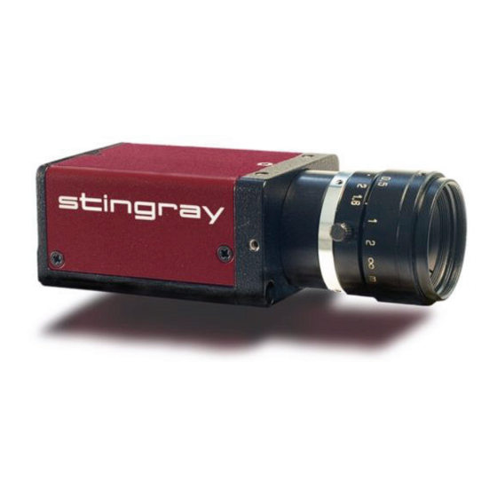
Scope of delivery
Each camera package consists of the following system components:
AVT Stingray camera
5 m cable with screw lock-
CD with driver
and documentation
Optional:
Optional: GOF cable
tripod adapter
Figure 1: System components
www
For more accessories visit the AVT website at:
http://www.alliedvisiontec.com/avt-products/accessories.html
AVT Stingray
V2.2.0
15 August 2008
Color version:
ing
Hoya C-5000 IR cut filter
(built-in)
B/w version:
Standard glass, no filter
(built-in)
Optional: HIROSE
connector for cable mount
HR10A-10P-12S
STINGRAY Instruction Leaflet V2.2.0
CE conformity
Info
•
AVT STINGRAY cameras are in conformity with the CE standard
and its underlying directions.
•
Board level models are delivered without housing. Because
housing design is critical to the electromagnetic interference
characteristics of a camera, no CE certification tests regarding
electromagnetic interference have been performed for board
level models. Users who design board level models into their
systems should perform appropriate testing regarding electro-
magnetic interference after the product design is completed.
Technical and ordering info
Info
•
Technical information:
support@alliedvisiontec.com
phone (for Germany): +49 (0)36428 677-270
phone (for USA): +1 978-225-2030
outside Germany/USA: Please check the link for your local
dealer.
http://www.alliedvisiontec.com/partner.html
•
Ordering and commercial information:
customer-care@alliedvisiontec.com
phone (for Germany): +49 (0)36428 677-230
phone (for USA): +1 978-225-2030
outside Germany/USA: Please check the link for your local
dealer.
http://www.alliedvisiontec.com/partner.html
Please note order number/text given in the following tables.
Camera I/O connector
Figure 2: Camera I/O connector pin assignment
Pin Signal
1
External GND
2
External Power
3
Camera Out 4
4
Camera In 1
5
Camera Out 3
6
Camera Out 1
7
Camera In GND
8
RxD RS232
9
TxD RS232
10
Camera Out Power In
11
Camera In 2
12
Camera Out 2
For maximum voltage levels see Hardware Installation Guide, Chapter STINGRAY
input descriptions.
3
STINGRAY Instruction Leaflet V2.2.0
1
9
2
10
8
3
11
12
7
4
6
5
Direction Level
Description
GND for RS232 and ext.
External Ground for RS232
power
and external power
+8...+36 V DC
Power supply
Out
Open emitter
Camera Output 4
(GPOut4)
default: -
In
U
(high) = 3 V...24 V
Camera Input 1
in
U
(low) = 0 V...1.5 V
(GPIn1)
in
default: Trigger
Out
Open emitter
Camera Output 3
(GPOut3)
default: Busy
Out
Open emitter
Camera Output 1
(GPOut1)
default: IntEna
In
Common GND for inputs Camera Common Input Ground
(In GND)
In
RS232
Terminal Receive Data
Out
RS232
Terminal Transmit Data
Common VCC for outputs
Camera Output Power
max. 36 V DC
for digital outputs (OutVCC)
In
U
(high) = 3 V...24 V
Camera Input 2
in
U
(low) = 0 V...1.5 V
(GPIn2)
in
default: -
Out
Open emitter
Camera Output 2
(GPOut2)
default: -
Table 1: Camera I/O connector pinning
STINGRAY Instruction Leaflet V2.2.0
2
4
Advertisement
Table of Contents

Related Manuals for Allied Vision AVT Stingray


Summary of Contents for Allied Vision AVT Stingray
- Page 1 AVT Stingray CE conformity Info • AVT STINGRAY cameras are in conformity with the CE standard and its underlying directions. • Board level models are delivered without housing. Because housing design is critical to the electromagnetic interference characteristics of a camera, no CE certification tests regarding electromagnetic interference have been performed for board level models.
- Page 2 We strongly recommend using only 1394b adapter use or transfer, nor may they be used on web sites. cards with screw-locks. Allied Vision Technologies GmbH 08/2008 • Make sure not to touch the shield of the camera cable All rights reserved.
Need help?
Do you have a question about the AVT Stingray and is the answer not in the manual?
Questions and answers