Table of Contents
Advertisement
Quick Links
Advertisement
Table of Contents

Related Manuals for AIC RSC-2ETS


Summary of Contents for AIC RSC-2ETS
- Page 1 RSC-2ETS Rackmount Chassis User's Manual UM_RSC-2ETS_v1.3_030921...
-
Page 2: Table Of Contents
Table of Contents Preface ������������������������������������������������������������������������������������������������ i Safety Instructions ������������������������������������������������������������������������������ ii About This Manual ����������������������������������������������������������������������������� iv Chapter 1� Product Features �������������������������������������������������������������� 1 1.1 Components ....................1 1.2 Specifications .................... 2 1.3 Feature ....................... 2 Chapter 2� Hardware Setup ���������������������������������������������������������������� 6 2.1 Top Cover ....................6 2.2 Power Supply Unit Module ............... - Page 3 Document Release History Release Date Version Update Content October, 2017 User's Manual release to public. April, 2019 Content update. August, 2020 logo update. Manual cover update. March, 2021 Technical Support update...
- Page 4 Copyright © 2017 AIC®, Inc� All Rights Reserved� This document contains proprietary information about AIC® products and is not to be disclosed or used except in accordance with applicable agreements.
-
Page 5: Preface
Disclaimer AIC® shall not be liable for technical or editorial errors or omissions contained herein. The information provided is provided "as is" without warranty of any kind. To the extent permitted by law, neither AIC®... -
Page 6: Safety Instructions
Safety Instructions Before you commence, please attentively r the following important discretions below. All cautions and warnings on the equipment or in the manuals should be circumspectly noted and reviewed. Always ground yourself to prevent static electricity. Always ground yourself to prevent static electricity. 請... - Page 7 • Ensure that the voltage of the power source is within the specification on the label when connecting the equipment to the power outlet. The current load and output power of loads must be within the specification. • This equipment must be firmly connected to reliable grounding before usage. Pay special attention to power supplied other than direct connections, e.g.
-
Page 8: About This Manual
LED descriptions. Chapter 4 Technical Support For more information or suggestion, please contact the nearest AIC® corporation representative in your district or visit the AIC® website: https://www.aicipc.com/en/index. It is our greatest honor to provide the best service for our customers. -
Page 9: Chapter 1� Product Features
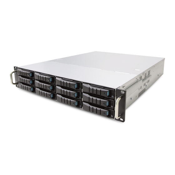
Chapter 1� Product Features RSC-2ETS is a flexible rackmount storage chassis with tool-less design. This product supports hot swappable HDDs and easy swap fans. For more information about our product, please visit our website at https://www.aicipc.com/en/index. Before removing the subsystem from the shipping carton, visually inspect the physical condition of the shipping carton. -
Page 10: Specifications
Chapter 1. Product Features 1�2 Specifications 1 x 12-port 12Gb SATA/SAS backplane mm : 430 x 560 x 88 Dimensions with 28-PHY expander chip and 3 (W x D x H) inches : 17 x 22 x 3.5 SFF-8643 connectors Backplane Options Industry Standard... - Page 11 Chapter 1. Product Features Front Panel 1 x USB 3.0 port 12 x 3.5" hotswap drive tray Power Button System Power LED System HDD Activity LED LAN LED System Alert LED ID LED ID button System Reset button...
- Page 12 Chapter 1. Product Features Rear Panel Option 1 2 x 2.5'' External hot swap drive bays 700W 1+1 redundant PSU PMBus 1.2 80+ Platinum 7 x PCIe 3.0 slots(low-profile) Option 2 2 x 2.5'' (7mm) SSD OS Option 3 2 x 2.5'' (15mm) internal SSD OS...
- Page 13 Chapter 1. Product Features Major Components 3 x 80 x 38mm PWM & low-power consumption hot swap fans 3 x 80 x 38mm PWM & low-power consumption hot swap fans 12" (W) x 9.6" (D) ATX compliant system board...
-
Page 14: Chapter 2� Hardware Setup
Chapter 2� Hardware Setup This chapter provides detailed instructions on hardware installation. 2�1 Top Cover Push the button on both sides Push the top cover backward. Lift up the top cover from the enclosure. -
Page 15: Power Supply Unit Module
Chapter 2. Hardware Setup 2�2 Power Supply Unit Module Push the latch towards the handle on the module. Pull the handle to remove it from the enclosure. -
Page 16: Fan Module
Chapter 2. Hardware Setup 2�3 Fan Module 2�3�1 Removing the Fan Grab and remove the fan module from the fan slot. RUBBER Pull the fan module up gently and take out the fan module by removing the rubbers out from the fan bar. -
Page 17: Installing The Fan
Chapter 2. Hardware Setup 2�3�2 Installing the Fan Align the fan module and make sure insert 4 screws with the opening in the enclosure. Make sure the 4 rubbers and connector insert firmly while fan module is inserted. -
Page 18: Hard Disk Drive
Chapter 2. Hardware Setup 2�4 Hard Disk Drive Release a drive tray by pressing the unlock button. Pull out the HDD tray handle and slide out the HDD tray. - Page 19 Chapter 2. Hardware Setup Insert the HDD into the tray. Directly place HDD into tool-less HDD tray untli it snaps. Please check if the screw holes on HDD match the dimples on HDD tray. HDD can also be screwed on HDD tray by reserve 2 screw holes at the bottom for optional screw mounting.
-
Page 20: Hdd Backplane
Chapter 2. Hardware Setup 2�5 HDD Backplane 2�5�1 Removing the HDD Backplane Unplug all connectors & HDDs from HDD backplane. Release the lock pin. - Page 21 Chapter 2. Hardware Setup Lift up and remove the blackplane to the a little bit up from hook then can get out.
-
Page 22: Installing The Hdd Backplane
Chapter 2. Hardware Setup 2�5�2 Installing the HDD Backplane Align the backplane with the hooks and insert it into the enclosure firmly. Lock the backplane. Follow the reverse order. -
Page 23: Slide Rail
Chapter 2. Hardware Setup 2�6 Slide Rail Release and detach the inner rail from the slide. P U S H ! - Page 24 Chapter 2. Hardware Setup Attach inner rail to the system. s l i d e i n n e r ra i l to l o c k Make sure spring lock firmly Reserve screw hole...
- Page 25 Chapter 2. Hardware Setup Attach outer rail to the rack. A L I G N P U S H L O C K ...
- Page 26 Chapter 2. Hardware Setup Verify ball bearing retainer is locked forward. Pull out the intermediate rail until locked out. Slide release tab and push system into rack.
-
Page 27: Chapter 3� Hardware Specification
Chapter 3� Hardware Specification This chapter provides detailed instruction guide on hardware instruction 3�1 HDD Backplane 3�1�1 Placement PCBA Placement... -
Page 28: Connector Location
Chapter 3. Hardware Specifications 3�1�2 Connector Location Connector Location JFAN1 JFAN2 JFAN3 JFAN3 JFAN3 JI2C3 JEXP2 JI2C4 JI2C0 JFAN4 SASHD3 SASHD3 SASHD3 JPMBUS JPMBUS JPMBUS JEXP_UART JEXP_UART JEXP_UART JPWR1 JPWR1 JPWR1 SASHD2 SASHD2 SASHD2 JMCU_DBG JMCU_DBG JMCU_DBG JPWR2 JPWR2 JPWR2 JMCU_UART JMCU_UART JMCU_UART... -
Page 29: Connector
Chapter 3. Hardware Specifications 3�1�3 Connector Power Connector – JPWR1 Description Description +12V +12V +3.3V MUTE_L +5VSTBY PSU_N1 PS_ON_L Power Connector – JPWR2 Description Description +12V +12V +12V +12V PMBUS Connector – JPMBUS Description PMBUS_CLOCK PMBUS_DATA... - Page 30 Chapter 3. Hardware Specifications I2C Connector – JI2C0, JI2C3, JI2C4 Description I2C_CLOCK I2C_DATA FAN Connector – JFAN1, JFAN2, JFAN3, JFAN4 Description I2C_CLOCK I2C_DATA Console for Expander – JEXP_UART Description Description DEBUG_RXD SMART_RXD +12V DEBUG_TXD SMART_TXD Remote Power Control – JMCU_UART Description Description DOWN_RXD...
- Page 31 Chapter 3. Hardware Specifications Console for MCU – JMCU_DBG Description MCU_RXD MCU_TXD 2.54mm Header for Front I/O – JFRONT • Fan number select Pin[5,6] Pin [3,4] Pin [1,2] Fan no. support Active Fan Locate Close Close Close No Fan Close Close Open One Fan...
- Page 32 Chapter 3. Hardware Specifications • Mute SW Description Remark MUTE Input(-) Active Low • Power/ID LED Description Remark For External LED(+) LED Anode For External LED(-) LED Cathode • Power SW Description Remark Power SW Input(-) Active Low • PMBUS Support Description Remark PMBUS_Disable_N...
-
Page 33: Led Indicator
Chapter 3. Hardware Specifications 3�1�4 LED Indicator LED1 LED1 LED1 LED2 LED2 LED2 SASHD Status LED SASHD Status LED SASHD Status LED LED5 LED5 LED5 Blue (On) HDD present HDD Activity LEDs Blue (Blinking) HDD Activity detected or Locate HDD HDD no connect or Power Off Normal HDD Fault/Status LEDs... -
Page 34: Jumper
Chapter 3. Hardware Specifications 3�1�5 Jumper JMCU_RST JMCU_RST JMCU_RST JMD_SEL JMD_SEL JMD_SEL Open Normal, default JMCU_RST Close Reset MCU Open Normal, default JMD_SEL Close Boot loader mode... -
Page 35: Drive Slot Map
Chapter 3. Hardware Specifications 3�1�6 Drive Slot Map... -
Page 36: Chapter 4� Technical Support
Chapter 4� Technical Support Taiwain, Global Headquarters South California, United States Address: No� 152, Section 4, Address: 21808 Garcia Lane Linghang N� Rd, Dayuan District, City of Industry, CA 91789, Taoyuan City 337, Taiwan United States Tel: +886-3-433-9188 Toll free: + 1-866-800-0056 Fax: +886-3-287-1818 Tel: +1-909-895-8989 Sales Email: sales@aicipc�com�tw...
Need help?
Do you have a question about the RSC-2ETS and is the answer not in the manual?
Questions and answers