Table of Contents
Advertisement
Quick Links
Advertisement
Table of Contents

Related Manuals for AIC RSC-1R


Summary of Contents for AIC RSC-1R
- Page 1 RSC-1R Rackmount Chassis User's Manual UM_RSC-1R_v1.3_020521...
-
Page 2: Table Of Contents
Table of Contents Preface ������������������������������������������������������������������������������������������������ i Safety Instructions ������������������������������������������������������������������������������ ii About This Manual ����������������������������������������������������������������������������� iv Chapter 1� Product Features �������������������������������������������������������������� 1 1.1 Components ....................1 1.2 Specifications .................... 2 1.3 Feature ....................... 2 Chapter 2� Hardware Setup ���������������������������������������������������������������� 5 2.1 Top Cover ....................5 2.2 Power Supply Unit Module ............... - Page 3 Document Release History Release Date Version Update Content July, 2016 User's Manual release to public. 1. New cover July, 2019 2. QIG update August, 2020 logo update February, 2021 Manual cover update...
- Page 4 Copyright © 2016 AIC®, Inc� All Rights Reserved� This document contains proprietary information about AIC® products and is not to be disclosed or used except in accordance with applicable agreements.
-
Page 5: Preface
Disclaimer AIC® shall not be liable for technical or editorial errors or omissions contained herein. The information provided is provided "as is" without warranty of any kind. To the extent permitted by law, neither AIC®... -
Page 6: Safety Instructions
Safety Instructions Before you commence, please attentively read the following important discretions below. All cautions and warnings on the equipment or in the manuals should be circumspectly noted and reviewed. Always ground yourself to prevent static electricity. Always ground yourself to prevent static electricity. 請... - Page 7 • Ensure that the voltage of the power source is within the specification on the label when connecting the equipment to the power outlet. The current load and output power of loads must be within the specification. • This equipment must be firmly connected to reliable grounding before usage. Pay special attention to power supplied other than direct connections, e.g.
-
Page 8: About This Manual
LED descriptions. Chapter 4 Technical Support For more information or suggestion, please contact the nearest AIC®corporation representative in your district or visit the AIC® website: https://www.aicipc.com/en/index. It is our greatest honor to provide the best service for our customers. -
Page 9: Chapter 1� Product Features
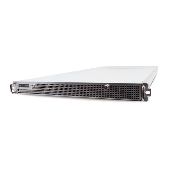
Chapter 1� Product Features RSC-1R is a flexible rackmount storage chassis with tool-less design. This product supports hot swappable HDDs and easy swap fans. For more information about our product, please visit our website at https://www.aicipc.com/en/index. Before removing the subsystem from the shipping carton, visually inspect the physical condition of the shipping carton. -
Page 10: Specifications
Chapter 1. Product Features 1�2 Specifications 3.5” hot swap mm : 438 x 890 x 44 Dimensions Drive Bays Internal (W x D x H) 2.5” 2 (15mm) inches : 17.2 x 35 x 1.7 2 x 4-port 12Gb SAS backplanes with single Backplanes Industry Standard EIA-RS310D... - Page 11 Chapter 1. Product Features Front Panel System Reset button LAN1 Power LED LAN2 Power LED System HDD Activity LED Power System LED Power On/Off Button Rear Panel...
- Page 12 Chapter 1. Product Features Top View Full height • 500W single PSU 80+ riser card Platinum • 600W redumdant PSU 80+ Gold 1 x40x28mm 4 x40x56mm PMW easy swap fan PMW easy swap fan 2.5-inch drive tray 3.5-inch drive tray...
-
Page 13: Chapter 2� Hardware Setup
Chapter 2� Hardware Setup 2�1 Top Cover Loosen the captive screw to release the top cover from the chassis. Push the cover towards the rear panel. Lift the cover upward to complete removal. ... -
Page 14: Power Supply Unit Module
Chapter 2. Hardware Setup 2�2 Power Supply Unit Module Extract the power supply unit by pushing the ejector while pulling the power supply unit. Pull the module completely out of the chassis. Install the new power supply unit by pushing it into the chassis. Ensure that the module is accurately inserted and locked into the chassis. -
Page 15: Fan Module
Chapter 2. Hardware Setup 2�3 Fan Module Unplug the cables and connectors. Lift the fan module upward. Check to carefully dislodge the rubber connectors from the attached bracket. Insert the new fan into the chassis. Verify to align the rubber connectors with the appropriate slot in the bracket. -
Page 16: Disk Drive Module
Chapter 2. Hardware Setup 2�4 Disk Drive Module 2�4�1 Disk Drive: 3�5-inch HDD Remove the top cover of the chassis. Refer to Section 2.1 for removal. Push the plunger and lift the disk drive out of the chassis. ... -
Page 17: Disk Drive: 2.5-Inch Ssd
Chapter 2. Hardware Setup 2�4�2 Disk Drive: 2�5-inch SSD Push the SSD towards the rear panel. Continue to push and lift the SSD out of the chassis. Lift the side that is closer to the front panel and then lift the other side for easier removal. ... -
Page 18: Slide Rail
Chapter 2. Hardware Setup 2�5 Slide Rail NOTE This sections provides a basic instruction for mounting the slide rail onto the system. Tool-less rails vary per order. The rail in this manaul may not exactly match the rail for your system. Please refer to the spefications or quick installation guide that came with your purchased product. - Page 19 Chapter 2. Hardware Setup Optional: Remove Metal Spacer for Aluminium Racks Metal Spacer Aligning the Front Bracket with the Mounting Hole. Push in to assembly the Front Bracket onto the Rack.
- Page 20 Chapter 3. Hardware Specifications Now the bracket is fixed onto the Rack. (Optional M6x10L screws are to secure the rails with posts if needed.) Refer to Step 3 & 4 to assemble the End Bracket onto the Rack.
- Page 21 Chapter 3. Hardware Specifications Assemble the inner channel onto the chassis using thescrews provided. Push the chassis with inner channels into Slide to complete Rack Installation.
-
Page 22: Chapter 3� Hardware Specification
Chapter 3� Hardware Specification 3�1 HDD Backplane 3�1�1 Placement Top view JLED_IN JSGPIO_SET SASHD JPWR JFAIL_IN JFAIL_OUT Backside veiw HDD1 HDD2 HDD3 HDD1 3�1�2 Internal Connector and Jumper MINI-SAS HD Connector (SASHD) Description Description HDD1_ACT HDD1_FAIL HDD2_ACT HDD2_FAIL HDD3_ACT HDD3_FAIL HDD4_ACT HDD4_FAIL Led Fail Status Header (JFAIL_IN) - Page 23 Chapter 3. Hardware Specifications Led Fail Header (JFAIL_OUT) Description +3V3 FAULT_DRIVE Power Connector (JPWR) Description Description +12V +12V SGPIO Jumper (JSGPIO_SET) Description Open Disable External Access LED input. Close Enable External Access LED input. Open Access LED from HDD Pin P11. Close Access LED from SGPIO.
-
Page 24: Drive Slot Map
Chapter 3. Hardware Specifications 3�1�3 Drive Slot Map FIRST LEVEL HBA Card SENCOND LEVEL HBA Card AND SO ON FIRST LEVEL MegaRaid Card AND SO ON... -
Page 25: Chapter 4� Technical Support
Chapter 4� Technical Support Taiwain, Global Headquarters South California, United States Address: No� 152, Section 4, Address: 21808 Garcia Lane Linghang N� Rd, Dayuan District, City of Industry, CA 91789, Taoyuan City 337, Taiwan United States Tel: +886-3-433-9188 Toll free: +7-4997019998 Fax: +886-3-287-1818 Tel: +1-909-895-8989 Fax: +1-909-895-8989#157...
Need help?
Do you have a question about the RSC-1R and is the answer not in the manual?
Questions and answers