
Related Manuals for GLAZING VISION Pitchvent


Summary of Contents for GLAZING VISION Pitchvent
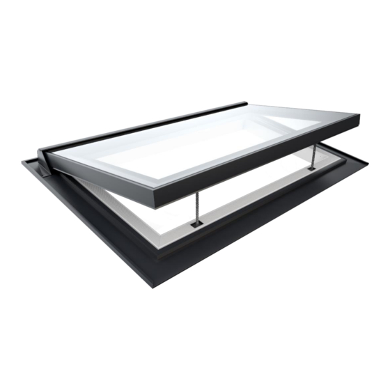
- Page 1 Pitchvent 202-INST-US-001 v1.0 – 11 Dec 2020 www.glazingvision.com 833-SKYDOOR (833-759-3667) sales@glazingvision.com...
-
Page 2: Table Of Contents
202-INST-US-001 v1.0 – 11 Dec 2020 Contents Section Description Page Introduction Safety Information Pre-Installation Preparation Preparation of the Roof Installation Procedure Chain Actuated Pitchvent Setup Manual Crank Pitchvent Setup Interior Finishing Need assistance? 833-SKYDOOR (833-759-3667) sales@glazingvision.com Page 2 of 25... -
Page 3: Introduction
Introduction Thank you for purchasing a Glazing Vision Pitchvent. In order to ensure that it gives you many years of service it is important that before commencing any work you read these instructions fully and ensure that they are strictly followed for a successful and trouble free installation. -
Page 4: Safety Information
These products can be very heavy. Extreme care must be taken during handling and installation. Full consideration should be given to how you will safely transport your roof window product from the delivery vehicle to the installation location. Glazing Vision strongly recommends that specialist, mechanical lifting equipment is employed. - Page 5 (please refer to terms and conditions of sale). Pre-Installation: • Glazing Vision products are heavy, fragile and of awkward shape and size. There may be uneven weight distribution due to the materials used and their design. • The weight(s) of each individual product (or product section) will be clearly marked on the product and will be communicated to clients before dispatch of goods.
-
Page 6: Pre-Installation Preparation
These cables will have identification labels on them (labels should not be removed until final installation). Please refer to Glazing Vision’s wiring diagrams for details of wiring requirements. Only the supplied PSU can be fitted to the unit, failure to connect this unit or wiring direct to the main power supply will invalidate the product warranty. - Page 7 202-INST-US-001 v1.0 – 11 Dec 2020 The switch used to control the operation of the Chain Actuated Pitchvent is a two button wall mounted control switch. This switch will allow you to operate and stop at any position between the fully open and closed positions. This switch also contains a tri-color LED to display the product status to the user.
-
Page 8: Preparation Of The Roof
Figure A is for illustrative purposes only and may not be suitable for your installation. These products can be very heavy. Glazing Vision strongly recommends that a structural engineer is consulted when designing the structure(s) that will support the product and the surrounding roof. Nothing in this manual constitutes a structural proposal. - Page 9 These products can be very heavy. Glazing Vision strongly recommends that a structural engineer is consulted when designing the structure(s) that will support the product and the surrounding roof. Nothing in this manual constitutes a structural proposal.
- Page 10 These products can be very heavy. Glazing Vision strongly recommends that a structural engineer is consulted when designing the structure(s) that will support the product and the surrounding roof. Nothing in this manual constitutes a structural proposal.
-
Page 11: Installation Procedure
All of the images in this guide are diagrammatic. They should be used as a reference only and may not be a true representation of your installation. Please refer to Glazing Vision’s sales drawings throughout the installation. - Page 12 Step 2 – Install the Sill Tilting Fillet Install a tilting fillet as shown (not supplied) - Glazing Vision recommends that a hardwood or treated softwood fillet is used. The sill tilting fillet should be at least the length of the external width of the product and have a minimum 5° fall over the fillet. Consider the distance required between the sill of the product and the fillet (figure 2 –...
- Page 13 Glazing Vision supplies woodscrews with the Pitchvent. If fixing to a support structure made from a material other than timber, ensure the correct type of screws or fixings have been sourced prior to commencing this step.
- Page 14 202-INST-US-001 v1.0 – 11 Dec 2020 Butyl Figure 4c – Continuous butyl loop on the underside of the product Fit the chosen lifting equipment to the unit and check that it is secure. Carefully lift the product to the installation site (roof) using strops underneath the wooden build frame/bocks. This is to ensure that the build frame/blocks do not separate from the product during the lift.
- Page 15 202-INST-US-001 v1.0 – 11 Dec 2020 Use as many/few packers as required Figure 4e – Fixing detail (from inside) Step 5 – Silicone the Head, Sill and Jambs Run a continuous thick fillet of silicone (supplied) along the entire length of the head, the sill and both jambs. Continuous fillet of silicone around the product...
- Page 16 202-INST-US-001 v1.0 – 11 Dec 2020 Step 6 – Apply the Butyl Tape to the Jambs Apply 2” butyl tape (supplied as part of flashing kit if specified, otherwise use approx. 1/16” double-sided butyl tape) to the full length of the gutter lip on both jambs (sides).
- Page 17 Step 8 – Install the Head Tilting Fillet Install a tilting fillet as shown (not supplied) - Glazing Vision recommends that a hardwood or treated softwood fillet is used. Fix the fillet to the rafters. Head fillet Figure 8 –...
- Page 18 202-INST-US-001 v1.0 – 11 Dec 2020 Head flashing tucked into head gutter of product Figure 9b – Head flashing installed Step 10 – Install the Head Apron Place the head apron in position (use the roofing underlay supplied as part of the flashing kit if specified, otherwise use roofing underlay of at least 39-3/8”...
- Page 19 Figure 12b – Example of a soaker Glazing Vision strongly recommends that the manufacture and installation of soakers is carried out by a competent lead- worker. Figure 12a is presented only as an example. The soakers described in figure 12b may not be suitable for your roof.
- Page 20 Tile to either side of the product, installing the soakers as you go. Figure 13b – Jambs tiled and soakers installed Tile above the product. Glazing Vision recommends that eaves tiles are used immediately above. Eaves tiles Figure 13c – Roof tiled above the head Do not apply any interior finishes yet.
-
Page 21: Chain Actuated Pitchvent Setup
Switch on the power. If the product cannot be seen when standing next to the wall mounted control switch, ask for assistance before continuing. When you are ready to run the Chain Actuated Pitchvent for the first time, press the close button on the wall mounted control switch. -
Page 22: Manual Crank Pitchvent Setup
202-INST-US-001 v1.0 – 11 Dec 2020 Manual Crank Pitchvent Setup Once the product has been installed, working from inside the building, remove the yellow transportation plate from the sill. Figure 14a – Transportation bracket removed Attach the base bracket and spacer (supplied) to the base frame of the product using the supplied screws – ensure that the bracket is correctly orientated (see figure 14e). - Page 23 202-INST-US-001 v1.0 – 11 Dec 2020 Wind the collar of the spindle all the way to the top (against the shoulder) before attaching the spindle to the frame bracket (this is essential as the glass will be in the way). Making sure that the shoulder of the spindle sits hard against the collar, unscrew a small length of the inner spindle, until it can connect to the lid bracket.
- Page 24 202-INST-US-001 v1.0 – 11 Dec 2020 Figure 14f – Raise the inner part of the spindle Figure 14g – Spindle attached to lid bracket Once set up is complete, check the product. Open and close the lid to check and make sure the lid closes with the spindle reaching the end of its travel without trying to apply too much force (which may pull the bracket off the framework when winding hard down on closing).
-
Page 25: Interior Finishing
Glazing Vision does not specify the finishes permitted except for the following stipulations: • The finish must be built up to the internal dimension of the product – see Glazing Vision’s sales drawings. • No interior metal component (for example edging strips for plastering) may touch any part of the product framework that is the outer color (RAL 7015 grey as standard).
Need help?
Do you have a question about the Pitchvent and is the answer not in the manual?
Questions and answers