
Related Manuals for Svan SVCC9070


Summary of Contents for Svan SVCC9070
- Page 1 HOOD USER GUIDE ENGLISH CAMPANA INCLINADA 90CM CRISTAL BLANCO_SVCC9070 CAMPANA INCLINADA 90CM CRISTAL NEGRO_SVCC9070N Read this manual prior to performing any task!
- Page 2 SVAN TRADING SL CIUDAD DE CARTAGENA 20 (FUENTE DEL JARRO) PATERNA 46988 VALENCIA Spain Telephone: +34 960 600 034 1, en_US This device is designed exclusively for domestic use 12.03.2019 HOOD USER GUIDE ENGLISH...
-
Page 3: Table Of Contents
Table of contents Table of contents Technical Drawing..................4 WARNING AND SAFETY PRECAUTIONS..........5 2.1 LETHAL RISK, DANGER OF POISONING......... 7 USAGE WITH AND WITHOUT CARBON FILTER........11 Carbon Filter Replacement..............12 CLEANING AND PREVENTIVE MAINTENANCE........13 5.1 ALUMINIUM FILTER CLEANING............13 5.2 Washing in Dishwasher.............. -
Page 4: Technical Drawing
Technical Drawing Technical Drawing Fig. 1: 3420 DIMENSIONED TECHNICAL DRAWING 12.03.2019 HOOD USER GUIDE ENGLISH... -
Page 5: Warning And Safety Precautions
WARNING AND SAFETY PRECAUTIONS WARNING AND SAFETY PRECAU- TIONS WARNING AND SAFETY PRECAU- Make sure that the installation place allows the user to easily TIONS unplug the power cable in case of This appliance can be used by any danger. children of 8 years and older, Do not touch your product's lamps people with physical, sensory or... - Page 6 WARNING AND SAFETY PRECAUTIONS Do not use non-fire-resistant fil- If the feeder cable is damaged, it tering materials instead of the filter. must be replaced by its manufac- turer or its authorized technical Do not operate your product service or any other personnel without filter, and do not remove qualified at the same level, in order the filters when the product is in...
-
Page 7: Lethal Risk, Danger Of Poisoning
WARNING AND SAFETY PRECAUTIONS LETHAL RISK, DANGER OF POISONING This warning does not apply to Fig. 2: Poisoning Danger uses without flue. Ventilated goods (e.g. gas, oil, wood or When electric cooker hood is used coal burning heaters, shower heaters, simultaneously with devices that water heaters) take combustion air use gas or other fuels, there must... - Page 8 WARNING AND SAFETY PRECAUTIONS LETHAL RISK, DANGER OF POISONING L WARNING L WARNING Electrocution hazard! Fire danger! – A malfunctioning device may – The oil residue in the oil filter cause electric shock. Never turn may catch fire.Clean the oil filter on a malfunctioning device.
- Page 9 WARNING AND SAFETY PRECAUTIONS LETHAL RISK, DANGER OF POISONING L WARNING NOTICE Risk of burn, risk of electric shock! If the feeder cable is damaged, it must be replaced by its manufac- – Allow the appliance to cool turer or its authorized technical before cleaning or maintenance service or any other personnel process.
- Page 10 WARNING AND SAFETY PRECAUTIONS LETHAL RISK, DANGER OF POISONING Damage reasons L CAUTION Damage hazard due to corrosion. Always run the appliance to prevent condensate formation while cooking. Condensates may cause corrosion damage. Replace the mal- functioning lamp right away to pre- vent overloading of other lamps.
-
Page 11: Usage With And Without Carbon Filter
USAGE WITH AND WITHOUT CARBON FILTER USAGE WITH AND WITHOUT CARBON FILTER Ventilated air mode You can use this appliance in exhaust air mode and ventilated air mode. Absorbed air is cleaned by the grease Exhaust air mode filters and an active carbon filter, and then it is transferred back to the The absorbed air is cleaned by the kitchen.Fig. -
Page 12: Carbon Filter Replacement
Carbon Filter Replacement Carbon Filter Replacement KARBON FİLTER Fig. 6: KARBON FİLTER This device can be used with Carbon Filter . 1-Place the carbon filter to its housing Fig. 6. 2-Please mount the carbon filter by turning it on the its right side and be sure that it is fixed.Fig. -
Page 13: Cleaning And Preventive Maintenance
CLEANING AND PREVENTIVE MAINTENANCE ALUMINIUM FILTER CLEANING CLEANING AND PREVENTIVE MAIN- TENANCE Do not use excessively effective, L CAUTION acidic or alkaline cleaning agents. For cleaning the metal grease fil- Cleaning and user maintenance of ters, clean the holder parts of the the appliance shall not be per- metal grease filters in the appli- formed by unattended children. -
Page 14: Washing In Dishwasher
CLEANING AND PREVENTIVE MAINTENANCE Hand Wash 5.3 Hand Wash Press the aluminium filter tab (1) and pull the aluminium filter to the direction of the arrow (Fig. 7). As you remove the aluminium filter, hold it with your other hand to –... -
Page 15: Appliance Position
APPLIANCE POSITION APPLIANCE POSITION Fig. 8: CİHAZIN KONUMU When the hood is installed, the product must have at least 65cm clearance with the electricity cookers and 75cm with cookers operating on gas or other fuels (Fig. 8). 12.03.2019 HOOD USER GUIDE ENGLISH... -
Page 16: Cleaning And Preventive Maintenance
CLEANING AND PREVENTIVE MAINTENANCE Recommendations for Energy Saving CLEANING AND PREVENTIVE MAIN- TENANCE 7.1 Installation and Unpacking of the Appliance Check that your appliance is not deformed. Report the transport issues imme- diately to transport operator. Any faults encountered shall be reported to the dealer, too. -
Page 17: Content Of Package
CONTENT OF PACKAGE CONTENT OF PACKAGE Fig. 9: CONTENT OF PACKAGE Product Installation Template Inner Flue 10- Ø6mm Plastic Dowel Outer Flue 11- Ø10mm Plastic Dowel 150/120mm Plastic Flue 12- 5.5x60 Wall Mount Screw Flue Connection Plate 13- 3.9x22 Flue Connection Plate 150mm Flue Adapter (Option) Screw Remote Control (Optional) -
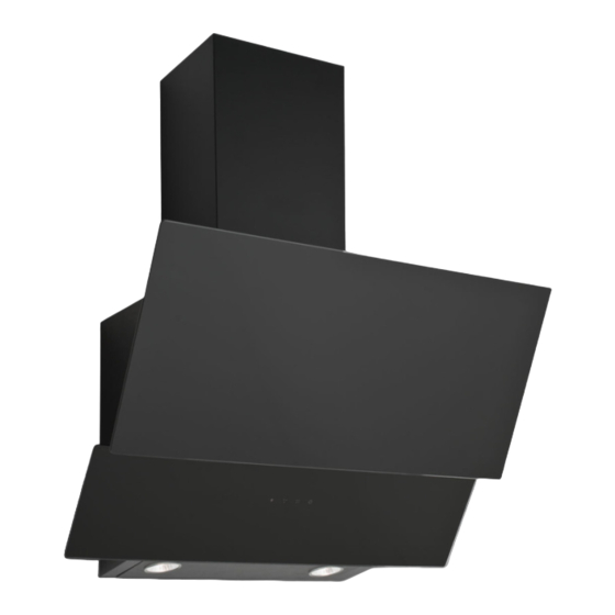
Page 18: Overview Of Hood
OVERVIEW OF hood OVERVIEW OF hood Fig. 10: OVERVIEW OF hood 1- Inner Flue 2- Outer Flue 3- Body 4- Control panel 5- Side Suction Plate / Glass 6- Cooker Lighting 12.03.2019 HOOD USER GUIDE ENGLISH... -
Page 19: Assembly Of Product
ASSEMBLY OF PRODUCT Installation Diagram and Components ASSEMBLY OF PRODUCT 10.1 Installation Diagram and Components Fig. 11: ASSEMBLY INSTALLATION AND COMPONENTS Inner Flue Body Outer Flue 4x Ø10mm Plastic Dowel Glass 4x 5.5x60 Wall Mount Screw Hanging Plate of Cooker Hood 2x 3.9x22 Screw Hanging Plate of Cooker Hood 10- Flue Connection Plate... - Page 20 ASSEMBLY OF PRODUCT Installation Diagram and Components Affix the assembly pattern on the wall, at the specified height (See the min- imum and maximum distances intended for the worktop, in the assembly pat- tern). Perforate points A, B, C and D (Fig. 11) Insert Ø10mm wall plugs into the holes drilled as A, B, C, and D and screw down the screws at the points A + B, in such a way as to remain 5mm space between the screw head and the wall (Fig.
-
Page 21: Air Exit Installation
AIR EXIT INSTALLATION AIR EXIT INSTALLATION Fig. 12: PLASTIC FLUE CONNEC- TION 1- Ø150/120mm Flue Adapter (Option) 2- 2x 3.5x9.5 Screw 3- Ø120/150mm Plastic Flue (Option) 4- Body Plastik bacayı (3) ürün gövdesine (4) takınız.() When required, attach the connec- tion part (1) on the plastic flue (3) and press firmly. -
Page 22: Assembly Of Sheet Metal Flues
ASSEMBLY OF SHEET METAL FLUES ASSEMBLY OF SHEET METAL FLUES Pull up to left the Internal Flue (1) using screws (2) and screw it on the flue connection sheet on the right and left (3) (Fig. 13). Fix the exterior flue to the right and left connection sheet at the rear side of the hood body from the lower side using 2 screws... -
Page 23: Use Of Product
USE OF PRODUCT 3 Spd Touch Product Usage USE OF PRODUCT 13.1 3 Spd Touch To activate timer function, press and hold any of buttons for 3 Product Usage seconds. When the timer function is activated the relevant button symbol will flash for 15 mins. -
Page 24: Using Push Button Product
USE OF PRODUCT Using Push Button Product 13.2 Using Push Button Product Fig. 15: push button Press this button to reset your product. Product will run on 1st speed level when this button is pressed. Product will run on 2nd speed level when this button is pressed. -
Page 25: Replacing The Lamps
REPLACING THE LAMPS Plug Lamp Replacement REPLACING THE LAMPS 14.1 Halogen Lamp Only self-protection tungsten halogen lamp or self-protection metal halide Replacement lamp must be used. L WARNING Disconnect the electrical supply of the hood. Leave the lamps to cool down first because they could burn your hands when they are hot. - Page 26 REPLACING THE LAMPS Plug Lamp Replacement It indicates the maximum power con- sumption of the lamp. A lamp with same power rating should be used when replacing the lamp. To find out the power rating used in the product, see the declaration label in the product.
-
Page 27: Authorized Service
AUTHORIZED SERVICE AUTHORIZED SERVICE If Lighting is Not Functioning: Make sure that the plug is plugged in, and that the fuses are intact. Check the bulbs. Make sure you unplugged the device before performing this check. Tighten the bulbs if they are loose; you can replace the bulbs if they still don't work. - Page 28 AUTHORIZED SERVICE Troubleshooting Fault description Cause Remedy Mains voltage must be 220-240 V, Product Does Not Work Check the power and product must be plugged into a connection. grounded socket. Mains voltage must be 220-240 V, Illumination lamp does Check the power and product must be plugged into a not operate connection.
-
Page 29: Technical Table
TECHNICAL TABLE TECHNICAL TABLE Supply Voltage 220 - 240 V 50Hz Insulation Class of Motor Insulation Class CLASS I This product complies with the 2014/30/EC (Regulation on Electro- magnetic Compliance) and 2014/35/EC (Regulation on Low Voltage Devices (LVD)) Directives. This device complies with the Directive on the Control of Waste Electrical and Electronic Equipment.
Need help?
Do you have a question about the SVCC9070 and is the answer not in the manual?
Questions and answers