
Subscribe to Our Youtube Channel
Related Manuals for Amit RRU-WEC/1201


Summary of Contents for Amit RRU-WEC/1201
- Page 1 RRU-WEC/1201 WTB / Ethernet / CAN gateway Operation manual Revision 1.00 rru-wec1201_g_en_100...
- Page 2 RRU-WEC/1201 AMiT, spol. s r.o. does not provide any warranty concerning the contents of this publication and reserves the right to change the documentation without obligation to inform anyone or any authority about it. This document can be copied and redistributed under following conditions: 1.
-
Page 3: Table Of Contents
RRU-WEC/1201 Contents History of revisions ..................4 Related documentation ................... 4 Used symbols ....................4 Definition of used abbreviations ............5 Definition of used terms ..............6 Introduction ..................7 Technical parameters ................8 4.1. Dimensions ....................11 4.2. Recommended drawing symbol ..............12 4.3. -
Page 4: History Of Revisions
RRU-WEC/1201 History of revisions Document name: rru-wec1201_g_en_100.pdf Revision Date Author of change Changes 21.10.2016 Škoch J. New document Related documentation SW for WTB/ETHERNET/CAN Gateway – Programmer’s manual file: tcn-gw-wec_ref_ms_en_xxx.pdf Used symbols Check documentation mentioned above Important note Danger of electric shock... -
Page 5: Definition Of Used Abbreviations
RRU-WEC/1201 1. Definition of used abbreviations Bus Administrator Electric Middle Distance Medium Attachment Unit Multifunction Vehicle Bus Message Data Process Data To Be Defined Train Communication Network Wire Train Bus 5/34 rru-wec1201_g_en_100... -
Page 6: Definition Of Used Terms
RRU-WEC/1201 2. Definition of used terms Bus Administrator MVB device with Bus Administrator functionality is able to work as MVB bus Master. This function supposes the device is able to transfer the process data and reports as well as transmit and receive the Device Status type information. -
Page 7: Introduction
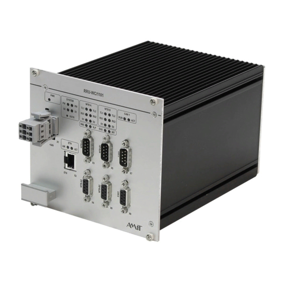
RRU-WEC/1201 3. Introduction RRU-WEC/1201 is a communication gateway which serves for transfer of process data and messages between WTB, ETH and CAN buses. Gateway is officially homologated and approved for international use according to UIC 556 standard. CAN bus communication protocol meets the requirements of EN 61375-3-3:2012. -
Page 8: Technical Parameters
RRU-WEC/1201 4. Technical parameters Number of WTB lines 1 (double line) 16 × LED Operation indication Galvanic isolation Yes, 1000 V AC. / 1 minute Fritting 1 Mbps ±0.01 % Communication rate Max. number of devices Max. segment length without repeater 860 m 120 Ω... - Page 9 RRU-WEC/1201 Power supply Nominal power supply voltage 24 V DC Maximum power consumption Max. 0.6 A Power supply voltage range 16.8 V DC to 30 V DC (permanent) Inrush current Max. 15 A / < 1 ms Galvanic isolation Yes, 1000 V AC. / 1 minute...
- Page 10 RRU-WEC/1201 According to EN 61373 standard, WTB gateway is classified in terms of vibrations into Category 1, Class B (mounting to vehicle body). Permissible supplying voltage drop-outs duration: max. 10 ms (Class S2 according to Chapter 3.1.1.2 of EN 50155:2007).
-
Page 11: Dimensions
RRU-WEC/1201 4.1. Dimensions 141,9 172,0 186,0 141,9 Obr. 1 - Physical dimensions of WTB gateway 11/34 rru-wec1201_g_en_100... -
Page 12: Recommended Drawing Symbol
RRU-WEC/1201 4.2. Recommended drawing symbol Following drawing symbol is recommended for RRU-WEC/1201 WTB gateway. RRU-WEC/1201 D-sub 2W2C, UNC 4-40 Ethernet D-sub DE-9 M WTB A1 D-sub DE-9 F WTB A2 D-sub DE-9 M WTB B1 D-sub DE-9 F WTB B2... -
Page 13: Block Diagram
WTB A2 WTB B1 WTB B2 CAN1 CAN1 CAN2 CAN2 Power Ethrenet interface interface interface interface 1.2 V 1.8 V DDR2 FPGA 2.5 V Power Power supply supply 24 V Obr. 3 - Block diagram of RRU-WEC/1201 WTB gateway 13/34 rru-wec1201_g_en_100... -
Page 14: Type Label
RRU-WEC/1201 4.4. Type label The unit has a type label attached to its left side. Included data are summarized in the table: Example of Description Data Note data on type – Logo AMiT Producer logo label – QR code Product QR code... - Page 15 RRU-WEC/1201 TYPE RRU-WEC/1201 AA00000 00-09-54-0C-FF-FF 1.00 POWER 24 V DC / 0.6 A WEIGHT 1.62 kg TEST OK-AM HiPot HiPot-OK DATE 01.04.2016 Obr. 5 - Location of type label (illustrative picture) 15/34 rru-wec1201_g_en_100...
-
Page 16: Conformity Assessment
RRU-WEC/1201 5. Conformity assessment WTB gateway RRU-WEC/1201, provided it is used in accordance with this manual, meets the requirements of NV616/2006 Czech governmental decree. The conformity assessment has been carried out in accordance with harmonized standard EN 50121-3-2:2006. Tested in accordance... -
Page 17: Other Tests
RRU-WEC/1201 5.1. Other tests RRU-WEC/1201 WTB gateway has been assessed and approved for use in railway applications according to standards: Tested in accordance Type of test Result with standard Railway applications – Electronic EN 50155:2007 Complies equipment used on rolling stock Railway applications –... -
Page 18: Power Supply
RRU-WEC/1201 6. Power supply WTB gateway RRU-WEC/1201 can be powered by 24 V DC from vehicle’s on- board network. 6.1. Powering from DC network Power supply voltage is connected to X1 D-sub 2W2 connector. Obr. 6 - Power supply connector location... -
Page 19: Communication Lines
RRU-WEC/1201 7. Communication lines 7.1. WTB WTB gateway RRU-WEC/1201 has a WTB interface with doubled line, according to EN 61375-2-1:2012 standard. Both lines are connected through D-sub DE-9 connectors. Connectors are fitted with M3 threaded nuts, that prevents the cable falling off due to vibrations or to be broken away. -
Page 20: Wtb Line State Indication
RRU-WEC/1201 Connector type: D-sub DE-9, socket Connector Signal/Description X4, X6 WTB line positive wire WTB line negative wire Not used Not used Not used Not used Not used Not used Not used 7.1.1 WTB line state indication Indication of WTB line state is provided by 16 LEDs in the middle part of front panel. -
Page 21: Ethernet
RRU-WEC/1201 7.2. Ethernet The Ethernet 100 Mbps interface allows to connect the WTB gateway to LAN network. Ethernet interface is fitted with M12 connector according to IEC 61375-3-4:2014 Obr. 9 - Location of Ethernet line connector M12 type M12 type connector according to EN 61375-3-4:2014... -
Page 22: Ethernet Line State Indication
RRU-WEC/1201 7.2.1 Ethernet line state indication Indication of Ethernet line state is provided by two LEDs, located above the RJ45 connector. Obr. 11 - Front panel LEDs detail (Ethernet) Description of Colour Description Green Gateway connection to Ethernet network Green... -
Page 23: Can
RRU-WEC/1201 7.3. CAN WTB gateway RRU-WEC/1201 is fitted with two galvanically isolated CAN interfaces. Both interfaces are equipped with two concatenated connectors. Terminating resistor is not included with plug-in card and can be connected through external terminating module TRM-CAN/F, TRM-CAN/M, RRC-TRM/A or RRC-TRM/B (see chapter 10.1 Ordering Information). -
Page 24: Can Lines Status Indication
RRU-WEC/1201 Connector type: D-sub DE-9, socket Connector Signal/Description X7 (CAN1) Not used X9 (CAN2) CAN1 line negative wire Galvanically isolated ground Not used Connector chassis Galvanically isolated ground CAN1 line positive wire Not used Not used 7.3.1 CAN lines status indication State of CAN lines is indicated by 4 LEDs on front panel. -
Page 25: Indications And Settings
RRU-WEC/1201 8. Indications and settings 8.1. System LEDs Obr. 14 - Front panel LEDs detail (System LEDs) LED colours Colour Yellow Green Green Description of Status Description Power supply voltage indication Blinks, T = 2 s Operation state Blinks, T =... -
Page 26: Service Mode And Factory Setting
RRU-WEC/1201 8.2. Service mode and factory setting Service mode is started and factory settings are restored through RSTR button. To press the button, use a tool with diameter max. 1.5 mm Service mode To restore the factory setting press and hold the RSTR button while gateway starts up. -
Page 27: Mounting, Installation Rules
9. Mounting, installation rules 9.1. Mounting instructions WTB gateway RRU-WEC/1201 is supplied in design for installation into 19“ subrack. After the installation in to the rack, WTB gateway must be secured with four screws in plastic sleeves on corners of WTB gateway. - Page 28 RRU-WEC/1201 Obr. 16 - Fixing, when mounting in to frame. Keep the free space at least 70 mm in front of the WTB gateway for attaching cables. It is very important to ensure that ambient temperature does not exceed the allowed limits.
-
Page 29: Mounting Template
RRU-WEC/1201 9.2. Mounting template All dimensions are stated in mm. 127,0 141,0 Obr. 17 - Mounting template for mounting into the frame 9.3. Installation rules PE terminal of WTB gateway power supply connector must be connected with local installation earthing terminal. -
Page 30: Ordering Information And Completion
RRU-WEC/1201 10. Ordering information and completion 10.1. Ordering Information WTB gateway RRU-WEC/1201 Complete, see chapter 10.2 Completion M12 cable set, plug, IP66, for AWG 24 – 28 Accessories M12M04D-MC/A CAN 02C-MC/A Power supply connector counterpart, D-sub 2W2C, UNC 4-40, crimping contact, metal cap, plug... -
Page 31: Packing
RRU-WEC/1201 11. Packing Unit is packed in bubble wrap and placed into paper box. Package dimensions are listed in chapter Technical parameters. Label Sticker on the box contains following information: Item Description TYPE RRU-WEC/1201 NETTO 1.62 kg BRUTTO 2.04 kg... -
Page 32: Storing
RRU-WEC/1201 12. Storing To prevent damage of the device, follow these rules. Device in a Device in original packaging must be stored under the conditions specified in package chapter 4. Technical parameters. Device must not come into contact with water, oil or any other liquids, that can damage the packaging. -
Page 33: Maintenance
RRU-WEC/1201 13. Maintenance WTB gateway requires no periodic control nor maintenance. Cleaning Depending on the way WTB gateway is used, it is necessary to clean the dust from the inside of the equipment from time to time. The WTB gateway can be cleaned in cut-off state and disassembled, by dry paintbrush or fine brush, alternatively by vacuum cleaner. -
Page 34: Waste Disposal
RRU-WEC/1201 14. Waste disposal Electronics The disposal of WTB gateway is subject to the regulations on handling electrical disposal waste. WTB gateway must not be disposed together with common public waste. It must be delivered to places specified for that purpose and recycled.
Need help?
Do you have a question about the RRU-WEC/1201 and is the answer not in the manual?
Questions and answers