Table of Contents
Advertisement
Quick Links
Advertisement
Table of Contents

Subscribe to Our Youtube Channel
Related Manuals for Amit RRU-WC/110x


Summary of Contents for Amit RRU-WC/110x
- Page 1 RRU-WC/110x WTB / CAN gateway Operation manual Version 1.00 rru-wc1101_g_en_100...
- Page 2 RRU-WC/110 AMiT, spol. s r.o. does not provide any warranty concerning the contents of this publication and reserves the right to change the documentation without obligation to inform any body or authority about it. This document can be copied and redistributed under following conditions: 1.
-
Page 3: Table Of Contents
RRU-WC/110 Contents History of revisions ..................4 Related documentation ................... 4 Definition of used abbreviaions ............5 Definition of used terms ..............6 Introduction ..................7 Technical parameters ................8 4.1. Dimensions ....................11 4.2. Recommended drawing symbol ..............12 4.3. -
Page 4: History Of Revisions
RRU-WC/110 History of revisions Document name: rru-wc1101_g_en_100.pdf Author: Jiří Březina Revision Date Changes 29. 6. 2012 New document Related documentation WTB/CAN Gateway Programming manual file: wtb-c11_1_ms_en_xxx.pdf i a i n in i e file: ap0029_en_xx.pdf Application N e in i e e ne ne file: ap0037_en_xx.pdf rru-wc1101_g_en_100... -
Page 5: Definition Of Used Abbreviaions
RRU-WC/110 1. Definition of used abbreviaions Bus Administrator Electrical Middle Distance Medium Attachment Unit Multifunction Vehicle Bus Message Data Process Data To Be Defined Train Communication Network Wire Train Bus 5/28 rru-wc1101_g_en_100... -
Page 6: Definition Of Used Terms
RRU-WC/110 2. Definition of used terms Bus Administrator MVB device with Bus Administrator functionality is able to work as MVB bus Master. This function supposes the device is able to transfer the process data and reports as well as transmit and receive the Device Status type information. Electric Middle Distance This is a type of physical interface of MVB line, where a twisted pair of shielded wires is used for interconnection with implementing of transformer coupling for... -
Page 7: Introduction
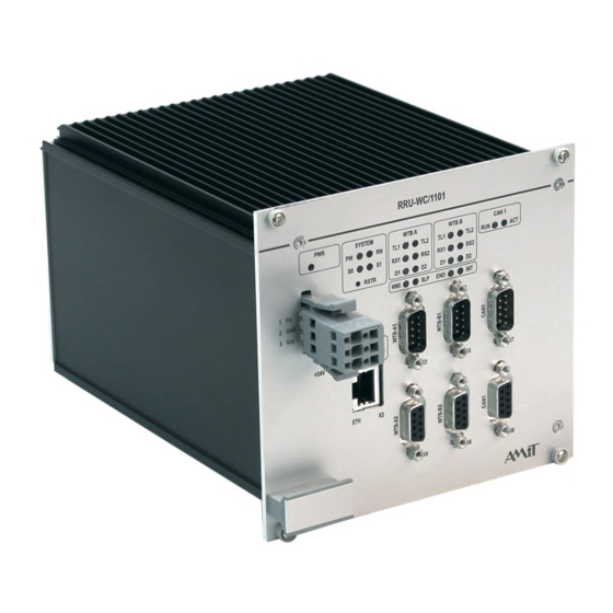
RRU-WC/110 3. Introduction RRU-WC/1101 is a communication gateway which serves for transfer of process data and messages between WTB and CAN buses. Gateway is oficially homologated and approved for international use according to UIC556 standard. CAN bus communication protocol meets the requirements of IEC 61375-3- 3:2012. -
Page 8: Technical Parameters
RRU-WC/110 4. Technical parameters Number of lines 1 (double line) 16 × L D Operation indication Galvanic separation Yes *) Dielectric strength 500 V AC / 1 minute Fritting 1 Mbps 0.01 % Data communication rate Max. number of devices Max. - Page 9 RRU-WC/110 Starting peak current Max. 30 A at 24 V DC Max. 48 A at 33.6 V DC Galvanic separation Yes *) Dielectric strength 500 V AC / 1 minute Connection point Connector WAGO 769-663 WAGO connector counterpart Connector WAGO 769-103 Wire cross section 0.75 mm to 2.5 mm...
- Page 10 RRU-WC/110 Permissible supplying voltage drop-outs duration: max 10 ms (Class S2 according to Chapter 3.1.1.2 of EN 50155:2007). For supply voltage switching are permissible conditions of C1 and C2 Class. Safety WTB gateway meets the SWSIL0 classification according to EN 50128:2011 Railway applications –...
-
Page 11: Dimensions
RRU-WC/110 4.1. Dimensions All dimensions are stated in mm. Fig. 1 - Physical dimensions of WTB gateway 11/28 rru-wc1101_g_en_100... -
Page 12: Recommended Drawing Symbol
RRU-WC/110 4.2. Recommended drawing symbol Following drawing symbol is recommended for RRU-WC/1101 WTB gateway. RRU-WC/1101 RJ45 Ethernet WAGO 769-663 D-sub DE-9 24 V WTB A1 D-sub DE-9 WTB A2 D-sub DE-9 WTB B1 D-sub DE-9 WTB B2 D-sub DE-9 CAN1 D-sub DE-9 CAN1 Fig. -
Page 13: Block Diagram
RRU-WC/110 4.3. Block diagram Ethernet WTB A1 WTB A2 WTB B1 WTB B2 CAN1 CAN1 Power Ethrenet interface interface interface 1.2 V ss. 1.8 V ss. DDR2 FPGA 2.5 V ss. 24 V ss. 5 V ss. 5 V ss. Power Power supply... -
Page 14: Conformity Assessment
RRU-WC/110 5. Conformity assessment Providing that WTB gateway from RRU-WC/1101 series is correctly used, it comply the requirements of Czech government decree NV616/2006. The compliance assessment has been performed in accordance with harmonized standard. EN 50121-3-2:2006. Tested in accordance Type of test Classification with standard EN 55011:2009... - Page 15 RRU-WC/110 Electromagnetic compatibility (EMC) – EN 61000-4-29:2000 S1, S2, C1, C2 Part 4-29: Testing and measurement techniques – Voltage dips, short inter- ruptions and voltage variations on d.c. input power port immunity tests Environmental testing – Part 2-1: Test EN 60068-2-1:2007 Complies A: Cold Environmental testing –...
-
Page 16: Power Supply
RRU-WC/110 6. Power supply WTB gateway RRU-WC/1101 can be powered by 24 V DC vehicle onboard network. ® PWR X1 Connector type: WAGO 769-663 (X-COM ), plug connector Connector Signal Meaning wiring Unit chassis. Power supply, ground Power supply +24 V DC rru-wc1101_g_en_100 16/28... -
Page 17: Communication Lines
RRU-WC/110 7. Communication lines 7.1. WTB WTB gateway RRU-WC/1101 has available a WTB interface with double line, according to IEC61375-1:2007 standard. Both lines are connected through D-sub DE9 connectors. Connectors are fitted with M3 threaded nuts, that prevents the cable falling off due to vibrations or to be broken away. -
Page 18: Wtb Line State Indication
RRU-WC/110 7.1.1 WTB line state indication Indication of WTB line state is provided by 16 LEDs in the middle part of front panel. Six from these LEDs in WTB A area indicates the state of line A and six LEDs in WTB B area indicates the state of line B; remaining four LEDs indicate the node state. -
Page 19: Ethernet
RRU-WC/110 7.2. Ethernet The Ethernet 100 Mbps interface allows to connect the WTB gateway to LAN network. The line, which is fitted with RJ45 connector according to IEEE802.3 can be used only for service. Ethernet line Connector type: RJ45, according to IEEE802.3 connector Connector Signal wiring... -
Page 20: Can
RRU-WC/110 7.3. CAN WTB gateway RRU-WC/1101 is fitted with single interface CAN with galvanic separation. Interface is equipped with two concatenated connectors. Terminating resistor is not included on plug-in card and can be connected through external termination module RRC-TRM/A or RRC-TRM/B. CAN1 line Connector type: D-sub DE-9, plug connectors... -
Page 21: Indications And Settings
RRU-WC/110 8. Indications and settings 8.1. System LEDs Fig. 8 - Front panel LEDs (System LEDs) LED colors Color Yellow Green Green Meaning of Status Meaning LEDs Lights Power supply voltage indication Blinks, T = 2 s Operation status Blinks, T = 200 ms Service mode Blinks FW update is running... -
Page 22: Service Mode And Factory Setting
RRU-WC/110 8.2. Service mode and factory setting Service mode is started and factory settings are restored through RSTR button. To press the button, use a tool with diameter max. 1.5 mm (e.g. match, or ballpoint refill). Service mode To restore the factory setting press and hold the RSTR button while gateway starts up. -
Page 23: Mounting, Installation Rules
RRU-WC/110 9. Mounting, installation rules 9.1. Mounting instructions WTB gateway RRR-WC/1101 is supplied for installation into 1 “ b a . W en needed, the gateway can be mounted into metal frame if conditions stated in next paragraph are observed. For mounting are used four screws with M3.5 thread (not included). -
Page 24: Holes For Mounting Into Frame
RRU-WC/110 Keep the free space at least 70 mm in front of WTB gateway for attaching the cables. It is very important to ensure that ambient temperature does not exceed the allowed limits. At the same time must be ensured that heat radiating equipments located nearby does not cause exceeding of these maximum temperatures. -
Page 25: Installation Rules
RRU-WC/110 9.3. Installation rules PE terminal of WTB gateway power supply connector must be connected with local installation earthing terminal. Cross-section of supplying conductors must be at least 0.75 mm All cabling must be carefully tied by cable ties to avoid the excessive connector pulling or prying. -
Page 26: Ordering Information And Completion
RRU-WC/110 10. Ordering information and completion 10.1. Ordering information WTB gateway RRU-WC/110x Complet, see chapter Completion Connector CAN 09F-MC/A WTB line connector counterpart D-sub DE-9 pin, M3, crimping counterparts pins, metal cap, socket inů, M , CAN 09M-MC/A Protikus konektoru linky WTB, D-sub DE- va í, me a i ý... -
Page 27: Maintenance
RRU-WC/110 11. Maintenance WTB gateway requires no periodic control nor maintenance. Cleaning Time after time with regard to way of usage, it is necessary to remove dust from device. The WTB gateway can be cleaned in cut-off state and disassembled, by dry paintbrush or fine brush, alternatively by vacuum cleaner. -
Page 28: Waste Disposal
RRU-WC/110 12. Waste disposal Electronics The disposal of WTB gateway is subject to the regulations on handling electrical disposal waste. Equipment must not be disposed together with common public waste. It must be delivered to places specified for that purpose and recycled. rru-wc1101_g_en_100 28/28...
Need help?
Do you have a question about the RRU-WC/110x and is the answer not in the manual?
Questions and answers