Table of Contents
Advertisement
Quick Links
Advertisement
Table of Contents

Related Manuals for Seltron ACD20


Summary of Contents for Seltron ACD20
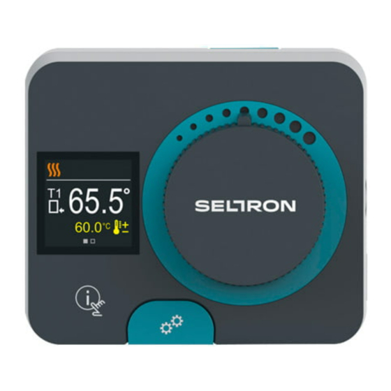
- Page 1 Constant temperature controller ACD20...
-
Page 3: Introduction
CONSTANT TEMPERATURE CONTROLLER ACD20 INTRODUCTION ACD20 controllers are modern microprocessor-controlled devices with an integrated actuator for the mixing valve and circulation pump control. They are produced in digital and SMT technology. They are designed to control constant temperature in various heating and cooling applications. They are most commonly used for the... -
Page 5: Table Of Contents
CONTENTS Introduction ..............................3 Appearance of the controller ........................6 Initial controller setup ..........................7 Basic screens ..............................11 Help ...................................14 Entering and navigating through the menu ..................14 Menu structure and description ......................15 Requested temperatures ......................... 16 Operation mode ............................18 Information ..............................20 Display ................................ -
Page 6: Appearance Of The Controller
APPEARANCE OF THE CONTROLLER 1. Button . Return back. 2. Button . Move to the left, decreasing. 3. Button . Move to the right, increasing. 4. Button . Menu entry, confirmation of selection. 5. USB port for software updates and connection to a personal computer. 6. -
Page 7: Initial Controller Setup
INITIAL CONTROLLER SETUP The controller is equipped with an innovative "Easy start" function, which allows the initial setting of the controller in just a few steps. Upon the first connection of the controller to the power supply network, the first step of the controller setup is displayed after the program version and logo The manual movement button must be removed for the setup. - Page 8 INITIAL CONTROLLER SETUP STEP 2 - SELECTING HEATING OR COOLING OPERATION Use the buttons to select the requested operating mode - heating or cooling. Confirm the selected operating mode by pressing If you've mistakenly selected the wrong operating mode, you can return to the operating selection with the button Later, you can change the operating mode in the "Operating mode"...
- Page 9 INITIAL CONTROLLER SETUP STEP 5: SETTING THE LOWER LIMIT FOR THE REQUESTED HEATING TEMPERATURE With the buttons you can set up the lower limit of the requested temperature in heating mode. Confirm the setup by pressing If you have accidentally set the wrong lower limit, you can return to the lower limit setting by pressing Later, you can change the lower limit setting of the requested heating temperature with the service...
- Page 10 INITIAL CONTROLLER SETUP STEP 8: SETTING THE LOWER LIMIT FOR THE REQUESTED COOLING TEMPERATURE With the buttons you can set up the lower limit of the requested temperature in cooling mode. Confirm the setup by pressing If you have accidentally set the wrong lower limit, you can return to the lower limit setting by pressing Later, you can change the lower limit setting of the requested cooling temperature with the service...
-
Page 11: Basic Screens
BASIC SCREENS All important data on the operation of the controller can be seen in the eight basic screens. Use the buttons to navigate between the basic screens. STATUS BAR Operating mode, notifications and alerts appear in the top third of the screen. Status bar Symbol Description... - Page 12 BASIC SCREENS Description Symbol Message In the event that the maximum temperature is exceeded or the safety function is activated, the controller notifies you with a yellow symbol on the display. When the maximum temperature is no longer exceeded or when a protection function has switched off, a gray simbol will turn on to note the recent event.
- Page 13 BASIC SCREENS HYDRAULIC SCHEME The screen shows the selected hydraulic scheme with the display of measured temperatures. Hydraulic scheme with screen showing the measured temperatures TIME AND DATE The screen shows the day of the week, the current time and date. Time and date Instructions for use | 13...
-
Page 14: Help
HELP By pressing the button we can start the display animation, which leads us to the additional settings menu. ENTERING AND NAVIGATING THROUGH THE MENU Requested temperatures Press the button to enter the menu. Navigate through the menu with the buttons and use the button to confirm your selection. -
Page 15: Menu Structure And Description
MENU STRUCTURE AND DESCRIPTION The menu consists of eight main groups: Requested Display Operation mode Information temperatures Statistics P parameters S parameters Factory settings Instructions for use | 15... -
Page 16: Requested Temperatures
REQUESTED TEMPERATURES In the menu, you can change the setting of the requested temperatures according to the selected hydraulic scheme. Requested temperatures Navigate through the menu with the buttons and use the button to confirm your selection. A new screen with temperatures will open. REQUESTED RETURN-PIPE TEMPERATURE Requested return- pipe temperature. - Page 17 REQUESTED TEMPERATURES REQUESTED STAND-PIPE TEMPERATURE Requested stand- pipe temperature Curent value of settings Default value Setting range Current value of the requested temperature Use the buttons to select the requested temperature and confirm it with the button. Exit the setting by pressing We can only set a temperature value that is available for the selected scheme.
-
Page 18: Operation Mode
OPERATION MODE In the menu, you can select the requested operation mode and other operation options. Dnevna Operation mode Operation temperatura Heating / cooling Manual Navigate through the menu with the buttons and use the button to confirm your selection. TURN OPERATION ON/OFF In the menu, turn the operation on or off. - Page 19 OPERATION MODE SELECTING HEATING OR COOLING OPERATION In the menu, select the requested heating or cooling operation mode. Heating /cooling symbol Heating / cooling selection Heating is active Cooling is active You can select heating or cooling with the buttons and confirm it with the button.
-
Page 20: Information
Navigate through the menu with the buttons and use the button to confirm your selection. ABOUT THE CONTROLLER The basic information about the controller is displayed on the screen. ACD20 Type of controller Company Logo Ver.:1.0r0 Sn: 12345678 Program version... - Page 21 INFORMATION MESSAGES A list of messages is displayed on the screen with the time and date of the individual message. Notification symbol List of notifications Navigate through the notifications with the buttons. Exit the screen with the button ERRORS A list of errors is displayed on the screen with the time and date of the individual errors.
- Page 22 INFORMATION DELETING THE MESSAGES AND ERRORS The list of messages and errors is deleted. The list of warnings for errors of all unconnected sensors is also deleted. Sensor errors that are essential for the controller operation cannot be deleted. The deletion must be confirmed by entering the 4-digit unlock code. Unlocking symbol Code entry field With the buttons...
-
Page 23: Display
DISPLAY The menu is for basic on-screen display settings. Display Language Time and date Illumination Menu exit Navigate through the menu with the buttons and use the button to confirm your selection. LANGUAGE SELECTION A list of available languages appears on the screen. Language symbol Language list Use the... - Page 24 DISPLAY TIME AND DATE SETTINGS You can set the exact time and date. Time and date symbol Day of the week Time and date With the buttons you can change the value and with the button you can move on to the next data. Exit display with the button ADJUSTING THE SCREEN BRIGHTNESS You can adjust the screen brightness.
- Page 25 DISPLAY SETTING THE MENU EXIT TIME You can set the time to automatically exit the menu Exit time symbol Current value of the exit time Default value Graphic display of the setting Setting range Current value With the buttons you can set the automatic exit time and confirm it with the .
-
Page 26: Statistics
STATISTICS The menu is intended to display detailed information on the operation of the controller. Statistics Graph Operation counter Change log Navigate through the menu with the buttons and use the button to confirm your selection. TEMPERATURE GRAPH A 24-hour temperature graph for all two temperature sensors is displayed on the screen. - Page 27 STATISTICS OPERATION COUNTER The display shows the number of operation hours of the R1 circulation pump output. Operation counter symbol Number of operation hours Counter reset By pressing the button for 5 seconds, you can reset the counter to 0. Exit the setting by pressing CHANGE LOG A list of changed P and S parameters of the controller is displayed on the screen.
- Page 28 USER P PARAMETERS The menu is used to display and set user parameters. The parameters are classified into group P1 - general settings. P parameters General Mixing circuit Energy source Navigate through the menu with the buttons. When you use the button to select the requested parameter group, a display will open describing the first parameter in the group.
-
Page 29: User P Parameters
USER P PARAMETERS Menu format setting: Parameter mark Parameter settings list Use the buttons to select the requested setting and confirm it with the button. Exit the setting with the button. Slider format setting: Parameter mark Current value Default value Graphic display of the setting Setting range... - Page 30 USER P PARAMETERS P1 - BASIC SETTINGS Para- Parameter name Parameter description Setting Default meter range value P1.1 Temperature round You set the accuracy of - 0.1 °C 0.5 °C displayed temperatures. - 0.2 °C - 0.5 °C - 1.0 °C Automatic shift of P1.2 With the help of a calendar,...
-
Page 31: Service S Parameters
SERVICE S PARAMETERS The menu is used to display and set user parameters. The parameters are classified into groups S1 - general settings, S2 - settings for the heating circuit and S3 - settings for the power source. S parameters General Mixing circuit Energy source... - Page 32 SERVICE S PARAMETERS Parameter Parameter is locked mark Current value With the buttons navigate through the parameters in the selected group. The parameter you want to change is selected by pressing the button. The S parameters are locked at the factory, so they must be unlocked by entering the 4-digit unlock code before changing.
- Page 33 SERVICE S PARAMETERS S1 - BASIC SETTINGS Para- Parameter name Parameter description Setting Default meter range value Hydraulic scheme S1.1 Selection of hydraulic scheme. 1 ÷ 3 Code for S1.2 This setting enables the change 0000 ÷ 9999 0001 unlocking the of code which is necessary to service unlock the service settings.
- Page 34 SERVICE S PARAMETERS S2 - MIXING CIRCUIT SETTINGS Para- Parameter name Parameter description Setting Default value meter range S2.1 Lower limit The lower limit of the possible 10 ÷ 70 °C Scheme 1 -50°C setting of the setting of the requested Scheme 2 -20°C requested temperature is set if operation...
- Page 35 SERVICE S PARAMETERS Para- Parameter name Parameter description Setting Default value meter range Mixing valve S2.9 Setting of mixing valve control 0.4 ÷ 2.5 I - constant frequency - how often mixing valve position is being controlled. Smaller value means low frequency, higher value means higher frequency S2.10 Mixing valve...
- Page 36 SERVICE S PARAMETERS Para- Parameter name Parameter description Setting Default value meter range S2.16 Boiler circulation This setting determines the 2.0 ÷ 8.0 °C 3.0 °C pump - switch off differential between the differential T2-T1 sensors T2 and T1, under which (°C) the circulation pump of the boiler is switched off.
- Page 37 SERVICE S PARAMETERS Para- Parameter name Parameter description Setting Default value meter range Minimum temp. S3.2 When the sensor T2 temperature 5 ÷ 70 °C 50 °C of sensor T2 in drops below the set minimum heating mode sensor T2 temperature, the (°C) controller shuts off the circulation pump and closes...
-
Page 38: Factory Settings
FACTORY SETTINGS The menu contains tools for resetting the controller to saved or factory settings. Factory settings Save settings Load settings Factory settings Navigate through the menu with the buttons. When you use the button to select the request command, a display will open for unlocking or confirming the command. -
Page 39: Clutch And Manual Valve Displacement
CLUTCH AND MANUAL VALVE DISPLACEMENT Pressing the clutch I. activates the manual valve displacement. You can now move the mixing valve by turning the button II. To return to automatic operation, press the clutch I. again. When the clutch is activated, the clutch symbol appears on the display. Instructions for settings | 39... - Page 40 CONTROLLER INSTALLATION In a dry and warm interior, the controller can be mounted directly on the mixing valve with the help of the accessories provided. Avoid close proximity to any strong electromagnetic fields. 40 | Installation instructions...
-
Page 41: Controller Installation
CONTROLLER INSTALLATION Scheme Mixing valve position Ring position Installation instructions | 41... -
Page 42: Controller Power Connection
CONTROLLER POWER CONNECTION Any project with an ACD controller must be based on calculations and plans that are solely yours and in accordance with applicable regulations. Images and texts in these instructions serve as examples and the issuer does not assume any responsibility for them. The liability of the issuer for unprofessional, incorrect and false information that can result in damage is explicitly excluded. -
Page 43: Operation Modes With Sensor Failure
OPERATION MODES WITH SENSOR FAILURE Sensor T1 is not connected or is faulty. - Heating: The controller switches on the circulation pump. In scheme 1, the mixing valve opens and in schemes 2 and 3 it closes. - Cooling: The controller switches off the circulation pump. Sensor T2 is not connected or is faulty. -
Page 44: Aux Function At Com Input
AUX FUNCTION AT COM INPUT The COM input can also be used for external actuation of the controller. The external actuation options are set with parameter S1.7. When a short circuit is detected at COM input, the following is activated: - switch from off to on of the heating if the parameter is set to S1.7 = Operation on. -
Page 45: Technical Data
TECHNICAL DATA General technical data - regulator Dimensions (W x H x D) ....................102 x 84 x 94 mm Regulator weight ..........................~ 800 g Regulator casing ......................PC - thermoplastic Supply voltage ........................230 V ~ , 50 Hz Own consumption ..........................0.5 VA Degree of protection ................ -
Page 46: Hydraulic Schemes
HYDRAULIC SCHEMES CAUTION! Installation diagrams show the principle of operation and do not contain all the auxiliary and safety elements! The applicable regulations must be observed during installation! SCHEME 1 - RETURN-PIPE - HEATING SCHEME 1 - RETURN-PIPE - COOLING 46 | Instructions for use... - Page 47 HYDRAULIC SCHEMES SCHEME 2 - SUPPLY - HEATING SCHEME 2 - SUPPLY - COOLING Instructions for use | 47...
- Page 48 HYDRAULIC SCHEMES SCHEME 3 - SUPPLY CONTROL BY LIMITING THE RETURN-PIPE TEMPERATURE - HEATING SCHEME 3 - SUPPLY CONTROL BY LIMITING THE RETURN-PIPE TEMPERATURE - COOLING 48 | Instructions for use...
- Page 49 NOTES | 49...
- Page 50 NOTES 50 | Instructions for use...
- Page 52 Seltron d.o.o. Tržaška cesta 85 A SL-2000 Maribor R4060011 v1.0 Slovenia Program v3.5r0 T: +386 (0) 2 671 96 00 F: +386 (0) 2 671 96 66 info@seltron.si www.seltron.eu 01MC060729 ©2020 We reserve the right to errors, changes and improvements without prior notice.
Need help?
Do you have a question about the ACD20 and is the answer not in the manual?
Questions and answers