
Related Manuals for Seltron AHC40


Summary of Contents for Seltron AHC40
- Page 1 AHC40 ENG Compact controller SLO Kompaktni regulator DEU Kompaktregler Regolatore compatto...
-
Page 3: Introduction
AHC40 COMPACT CONTROLLER INTRODUCTION AHC40 is a modern weather-compensated heating controller. Its design is compact and it comes with a mixing valve actuator. English 3... -
Page 4: Table Of Contents
CONTENTS Introduction ..........................3 INSTRUCTIONS FOR USE Appearance of the controller ....................5 Controller setup at the first start-up ..................6 Step 1 – Language selection ..................6 Step 2 – Selection of hydraulic schematic ..............6 Step 3 – setup of heating curve slope ................7 Step 4 –... -
Page 5: Instructions For Use
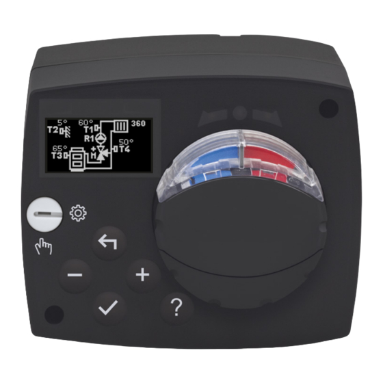
INSTRUCTIONS FOR USE APPEARANCE OF THE CONTROLLER 1. Graphic display 2. Manual operation clutch 3. Key Move backwards 4. Key Move left or reduction 5. Key Menu entry or selection confirmation 6. Key Move right or increase 7. Key Help 8. -
Page 6: Controller Setup At The First Start-Up
CONTROLLER SETUP AT THE FIRST START-UP The controller features an innovative solution “Easy start" allowing the initial setup of the controller in only four steps. Upon the first connection of the controller to the power supply network, the first step of the controller setup is displayed after the program version and logo. -
Page 7: Step 3 - Setup Of Heating Curve Slope
STEP 3 – SETUP OF HEATING CURVE SLOPE Setup the heating curve slope. Change the value with the keys Confirm the selected value by pressing Confirm the heating curve slope with the key If the wrong value has been selected in error, return to slope re-selection by pressing The heating curve slope can be changed with the P2.1 user parameter later STEP 4 –... -
Page 8: Graphic Lcd
GRAPHIC LCD All relevant data on the operation of the controller can be seen on the graphic LCD. DESCRIPTION AND APPEARANCE OF THE DISPLAY Room unit Operating mode and Notifications and Hydraulic schematic with user functions errors the temperature display Temperature, protection functions and display of other data Data display:... -
Page 9: Symbols For The Description Of The Operating Mode
SYMBOLS FOR THE DESCRIPTION OF THE OPERATING MODE Symbol Description Space heating Cooling Operation based on the time program – day intervals. * Operation based on the time program – night intervals. * Operation based on to the preferred day-time temperature. Operation based on to the preferred night-time temperature. -
Page 10: Symbols For The Display Of Temperatures And Other Data
SYMBOLS FOR THE DISPLAY OF TEMPERATURES AND OTHER DATA Symbol Description The measured temperature value Room temperature Outdoor temperature Temperature of the boiler or heat source Temperature of the supply line The temperature of the return line Temperature value measured with sensors T1, T2, T3 and T4 T1, T2, T3, T4 Temperature value measured with a room sensor or room unit Outdoor temperature, obtained through the BUS connection... -
Page 11: Symbols For Notifications And Warnings
SYMBOLS FOR NOTIFICATIONS AND WARNINGS Symbol Description Notifications In case of a transgression of the maximum temperature or activation of the protection function, the controller will trigger a warning with flashing of the symbol on the display. If the maximum temperature is no longer exceeded or if the protection function is already switched off, the lit-up symbol will indicate a recent event. -
Page 12: Menu Entry And Navigation
MENU ENTRY AND NAVIGATION To enter the menu press to move around the menu, and to confirm your selection. Return to the previous display by pressing If no key is pressed for 15 seconds, the display becomes dimmed. After the delay of the display switch-off, the display will switch off. - Page 13 Switch-off Selection of cooling or heating operation Manual operation TIME PROGRAMS First time program Second time program Third time program Fourth time program BASIC SETTINGS User language Time and date Display settings Delay for the switch-off of the display and automatic exit from the menu DATA REVIEW Graphic display of temperatures according to days of the last week Detailed graphic display of temperatures for the current day...
-
Page 14: Temperature Setup
SERVICE PARAMETERS General service settings Service settings for the heating circuit Service settings for energy sources SPECIAL PARAMETERS Parameters for floor foundation drying FACTORY SETTINGS Reset of the controller parameters Reset of the controller and restart of the first setup Reset of time programs Save user settings Load user settings... -
Page 15: User Functions
USER FUNCTIONS User functions provide additional comfort and benefits in using the controller. In the menu, the following user functions are available: PARTY operating mode PARTY function allows operation based on the preferred comfortable temperature. Select the function PARTY with the keys turn it on by pressing . -
Page 16: Operating Mode Selection
OPERATING MODE SELECTION In the menu, choose the preferred operating mode of the controller. Operation based on the selected time program Operation is based on the selected time program. Operation based on the daily temperature Operation is based on to the preferred day-time temperature. Operation based on the night-time temperature Operation is based on the preferred night-time temperature. -
Page 17: Selection And Setup Of Time Programs
Manual operating mode This mode is used for testing the control system or in the event of a failure. The control output can be manually switched on, switched off or automatic operation can be selected. Use the keys , to move among individual outputs R1, M+ or M-. - Page 18 With the keys , select the day to change the course of the program for or the one to copy in other days. With the keys select the icon for edit- ing and or the icon for copying the time program. Editing of the time program A new display will open up showing the time program and three icons for changing the program.
-
Page 19: Basic Settings
BASIC SETTINGS The menu is intended for setting up the language, time, date and display. User language Select the preferred user language with the keys and confirm it by pressing Exit the setup by pressing Time and date Set up the exact time and date in the following way: Use the keys , to move among individual data. - Page 20 Display setup The following setup is available: delay for the switch-off of the display and automatic exit from the menu. Confirm the preferred setup by pressing A new display will open up: Current value setup (numerical dis- Graphic play) symbol The last confirmed setup Current value value...
-
Page 21: Data Review
DATA REVIEW The menu has icons to access the data about the operation of the controller: TEMPERATURE DISPLAY FOR A PERIOD OF ONE WEEK Graphic display of the temperature curve for every day for each sensor. Temperatures are recorded for one week of operation retrospectively. DETAILED DISPLAY OF TEMPERATURES FOR THE CURRENT DAY Detailed graphic display of the temperature curve in the current day for each sensor. -
Page 22: Instructions For Service Settings
INSTRUCTIONS FOR SERVICE SETTINGS CONTROLLER PARAMETERS All additional settings and adjustments of the controller operation shall be executed using parameters. User, service and special parameters are located on the second and third displays of the menu. USER PARAMETERS User parameters are arranged in groups P1 – general settings, P2 – heating circuit settings and P3 –... - Page 23 General settings: Para- Parameter name Parameter description Setup range Default value meter P1.1 AUTOMATIC SWITCHO- Automatic switch-on or switch-off of heating 0–NO VER SUMMER/WINTER depending on the average one-day outdoor tem- 1–YES perature can be enabled with the setup. P1.2 AVERAGE OUTDOOR Set up the average one-day outdoor temperature 10 ÷...
-
Page 24: Heating Curve
Heating circuit settings: Para- Parameter name Parameter description Setup range Default meter value P2.1 HEATING CURVE STEEP- 0.5–floor The heating curve steepness informs the user of the 0.1 ÷ 2.6 NESS required temperature of heating devices at certain heating outdoor temperature. See section “Heating curve". 1.0–radia- tors P2.2... - Page 25 curve (parameter P2.2). If the room temperature drops when the outdoor temperatures are lower, the slope is too low so it should be increased. If the room temperature rises when the outdoor temperatures are lower, the slope is too high so it should be decreased. The increase or decrease of the slope should not be greater than 0.1 to 0.2 unit during one observation.
- Page 26 Diagram of cooling curves outdoor temperature 26 English...
-
Page 27: Service Parameters
SERVICE PARAMETERS Service parameters are arranged in groups S1 – general settings, S2 – heating circuit settings and S3 – settings for boiler or heat source. Many other features and adjustments of the controller operation can be chosen with service parameters. If the preferred group of parameters is selected in in the menu, a new display will open up: Parameter Current parameter... - Page 28 Use keys to select the number to change and press If the number is flashing, it can be changed it with the keys and confirmed by pressing If the correct code is entered, the controller unlocks parameters and return to the selected parameter. Exit the option for entering the unlock code by press- Factory set up code is 0001.
- Page 29 Para- Parameter name Parameter description Setup range Default meter value S1.10 BUILDING TYPE Set up the type (time constant) of the heated building. 0 ÷ 12h (TIME CONSTANT) Select higher value for massive and well insulated con- structions. Select lower value for minor and poorly insulated constructions.
- Page 30 Para- Parameter name Parameter description Setup range Default meter value S2.9 MIXING VALVE I – The setup indicates how intensely the controller corrects 0.4 ÷ 2.5 CONSTANT the position of the mixing valve in constant deviation of the stand-pipe. A lower value means shorter movements and a higher value larger correction positions of the mixing valve.
-
Page 31: Special Parameters
SPECIAL PARAMETERS Parameters for floor foundation drying are in the group F1. Procedures for the F parameters setup is the same as the procedure for the setup of user and service parameters. Parameters for floor foundation drying: Para- Parameter name Setup range Default meter... -
Page 32: Factory Settings
FACTORY SETTINGS Tools for help in the controller setup can be found in the menu. The following features are available: RESET OF CONTROLLER PARAMETERS All parameter settings (except S1.1) are restored to factory values. RESET OF THE CONTROLLER AND RESTART OF THE FIRST SETUP Setup will restore all parameters to factory values. - Page 33 stand-pipe and room temperature, at which the mixing valve closes, can be increased or reduced. If heating is not required or not included, the value 4°C will show as the calcu- lated temperature and the circulating pump will switch off with a delay – S2.15 parameter. Other operating options of the pump can also be selected with the S2.4 parameter.
-
Page 34: Operating Modes In The Event Of Sensor Failure
OPERATING MODES IN THE EVENT OF SENSOR FAILURE The outdoor sensor is not connected or is defective. - Heating: The controller operates as the P-controller depending on the deviation of the room temperature. - Cooling: The controller operates as a room thermostat by limiting the minimum stand temperature. The outdoor and room sensor are not connected or are defective. -
Page 35: Installation Instructions
INSTALLATION INSTRUCTIONS CONTROLLER INSTALLATION Install the controller with the supplied tools directly onto the mixing valve. English 35... -
Page 36: Electrical Connection Of The Controller
ELECTRICAL CONNECTION OF THE CONTROLLER Each project with the AHC controller should be based on calculations and plans that are exclusively yours and in accordance with the applicable regula- tions. Pictures and text in this instruction are only an example and the publish- er shall not be held liable. -
Page 37: Connection Of The Rcd Room Unit
CONNECTION OF THE RCD ROOM UNIT The controller allows the connection of the digital RCD room unit. It measures the room temperature and enables the setup of the preferred day-time and night-time temperature and operating mode selection. One RCD room unit can be connected to one controller. white BUS CONNECTION OF THE AHC CONTROLLERS A random number of AHC regulators can be interconnected with the BUS connection. -
Page 38: Bus Connection Of The Wdc And Ahc Controllers
BUS CONNECTION OF THE WDC AND AHC CONTROLLERS A random number of WDC and AHC regulators can be interconnected with the BUS connection. The first or the main controller physically controls heat sources, and the other ones only heat circuits. The outdoor sensor and the sensor of the heat source temperature must be connected to the first controller. -
Page 39: Technical Data
TECHNICAL DATA: General technical data – controller Dimensions (W x H x D) ..........102 x 84 x 94mm Weight of the controller ..........~800 g Housing of the controller ........... ASA and PC – thermoplastic Supply voltage ............230VAC, 50Hz Consumption ............. -
Page 40: Disposal Of The Old Electrical And Electronic Equipment
DISPOSAL OF THE OLD ELECTRICAL AND ELECTRONIC EQUIPMENT Disposal of the old electrical and electronic equipment (applies to the Member States of the European Union and other European countries that have a separate waste collection system). This symbol on a product or packaging indicates that it should not be dis- posed of as household waste. -
Page 41: Einführung
KOMPAKTREGLER AHC40 EINFÜHRUNG Der AHC40 ist ein moderner wettergesteuerter Heizungsregler. Er ist in einer kompakten Ausführung gefertigt, zusammen mit einem motorbetriebenen Mischventil. Deutsch 41... - Page 42 INHALTSVERZEICHNIS Einführung ...........................41 BEDIENUNGSANLEITUNG Aussehen des Reglers ......................43 Reglereinstellungen bei der ersten Inbetriebnahme ............44 1. Schritt – Sprachauswahl ..................44 2. Schritt – Auswahl des Hydraulikschemas ...............44 3. Schritt – Einstellung der Steigung der Heizkurve ...........45 4. Schritt – Auswahl der Öffnungsrichtung des Mischventils ........45 Grafisches LCD-Display ......................46 Beschreibung und Aussehen des Bildschirms ............46 Symbole für die Beschreibung der Betriebsart ............47...
-
Page 43: Aussehen Des Reglers
BEDIENUNGSANLEITUNG AUSSEHEN DES REGLERS 1. Grafisches Display 2. Kupplung für den manuellen Betrieb. 3. Taste . Schritt zurück. 4. Taste . Bewegung nach links oder Verringerung. 5. Taste . Zugang zum Menü oder Bestätigung der Auswahl. 6. Taste . Bewegung nach rechts oder Vergrößerung. 7. -
Page 44: Reglereinstellungen Bei Der Ersten Inbetriebnahme
REGLEREINSTELLUNGEN BEI DER ERSTEN INBETRIEBNAHME Der Regler ist mit der innovativen Lösung „Easy Start“ ausgestattet, die die Ersteinstellung des Reglers in nur vier Schritten ermöglicht. Beim ersten Anschluss des Reglers am Netz erscheint auf dem Display nach der Anzeige der Programmversion und des Logos der erste Schritt des Einstellungsverfahrens des Reglers. -
Page 45: Schritt - Einstellung Der Steigung Der Heizkurve
3. SCHRITT – EINSTELLUNG DER STEIGUNG DER HEIZKURVE Einstellung der Steigung der Heizkurve. Der Wert wird mit den Tasten geändert. Der eingestellte Wert wird mit der Taste bestätigt. Der Regler erfordert die Bestätigung der Steigungsein- stellung der Heizkurve mit der Taste Wenn Sie versehentlich den falschen Wert ausgewählt haben, kehren Sie mit der Taste zur Steigungsein-... -
Page 46: Grafisches Lcd-Display
GRAFISCHES LCD-DISPLAY Alle wichtigen Daten bezüglich der Funktion des Reglers werden auf dem grafischen LCD- Display angezeigt. BESCHREIBUNG UND AUSSEHEN DES BILDSCHIRMS Raumeinheit Betriebsart und Benut- Meldungen und Hydraulikschema mit zerfunktionen Fehler Temperaturanzeige Temperaturen, Schutzfunktionen und Anzeige anderer Daten Datenanzeige auf dem Bildschirm: Betriebsart, Benutzerfunktionen, Meldungen und Fehler werden in der oberen Hälfte des Bildschirms angezeigt. -
Page 47: Symbole Für Die Beschreibung Der Betriebsart
SYMBOLE FÜR DIE BESCHREIBUNG DER BETRIEBSART Symbol Beschreibung Raumheizung. Kühlung. Betrieb nach dem Zeitprogramm – Tagesintervall. * Betrieb nach dem Zeitprogramm – Nachtintervall. * Betrieb nach der gewünschten Tagestemperatur. Betrieb nach der gewünschten Nachttemperatur. Abschaltung. Manueller Betrieb. * Die Nummer bezeichnet das ausgewählte Zeitprogramm SYMBOLE DER BENUTZERFUNKTIONEN Symbol Beschreibung... -
Page 48: Symbole Für Die Anzeige Von Temperaturen Und Anderen Daten
SYMBOLE FÜR DIE ANZEIGE VON TEMPERATUREN UND ANDEREN DATEN Symbol Beschreibung Gemessene Temperatur. Raumtemperatur. Außentemperatur. Kessel- oder Wärmequellentemperatur. Temperatur der Steigleitung. Temperatur der Rücklaufleitung. T1, T2, T3, T4 Temperatur, gemessen mit den Sensoren T1, T2, T3 und T4. Temperatur, gemessen mit dem Raumsensor oder der Raumeinheit. Außentemperatur, ermittelt über die BUS-Verbindung. -
Page 49: Symbole Für Meldungen Und Hinweise
SYMBOLE FÜR MELDUNGEN UND HINWEISE Symbol Beschreibung Meldungen Im Fall einer Überschreitung der Höchsttemperatur oder der Ein- schaltung der Schutzfunktion, warnt der Regler durch Blinken dieses Symbols auf dem Display. Wenn die Höchsttemperatur nicht mehr überschritten ist oder sich die Schutzfunktion bereits abgeschaltet hat, macht das leuchtende Symbol auf das kürzlich erfolgte Ereignis aufmerksam. -
Page 50: Zugang Und Navigation Durchs Menü
ZUGANG UND NAVIGATION DURCHS MENÜ Für den Zugang zum Menü drücken Sie die Taste Durch das Menü bewegen Sie sich mit den Tasten , mit der Taste bestätigen Sie Ihre Auswahl. Durch Drücken der Taste kehren Sie zum vorherigen Bildschirm zurück. Wenn Sie 15 Sekunden lang keine Taste drücken, verringert sich die Bild- schirmhelligkeit. - Page 51 Abschaltung. Betriebsauswahl Heizung oder Kühlung. Manueller Betrieb. ZEITPROGRAMM Erstes Zeitprogramm. Zweites Zeitprogramm. Drittes Zeitprogramm. Viertes Zeitprogramm. GRUNDEINSTELLUNGEN Benutzersprache. Zeit und Datum. Displayeinstellungen. Verzögerung der Bildschirmabschaltung und automatisches Verlassen des Menüs. PRÜFUNG VON DATEN Grafische Darstellung der Temperaturen nach Tagen für den Zeitraum der letzten Woche. Detaillierte grafische Darstellung der Temperaturen des laufenden Tages.
-
Page 52: Temperatureinstellung
SERVICEPARAMETER Allgemeine Serviceeinstellungen. Serviceeinstellungen des Heizkreislaufs. Serviceeinstellungen von Wärmequellen. BESONDERE PARAMETER Parameter für das Trocknen von Estrich. WERKSEINSTELLUNGEN Zurücksetzen der Parameter des Reglers. Zurücksetzen des Reglers und Neustart der ersten Einstellung. Zurücksetzen der Zeitprogramme. Speichern der Benutzereinstellungen. Laden der Benutzereinstellungen. TEMPERATUREINSTELLUNG Im Menü... -
Page 53: Benutzerfunktionen
BENUTZERFUNKTIONEN Die Benutzerfunktionen ermöglichen zusätzlichen Komfort und Nutzen bei der Benutzung des Reglers. Im Menü stehen folgende Benutzerfunktionen zur Verfügung: Betriebsart PARTY Die Funktion PARTY ermöglicht das Einschalten des Betriebs gemäß der gewünschten Komforttemperatur. Mit den Tasten wählen Sie die Funktion Party aus und bestätigen sie mit der Taste . -
Page 54: Auswahl Der Betriebsart
AUSWAHL DER BETRIEBSART Im Menü wählen Sie die gewünschte Betriebsart des Reglers aus. Betrieb nach dem ausgewählten Zeitprogramm Betrieb nach dem ausgewählten Zeitprogramm. Betrieb nach der Tagestemperatur Betrieb nach der gewünschten Tagestemperatur. Betrieb nach der Nachttemperatur Betrieb nach der gewünschten Nachttemperatur. Abschaltung Der Regler ist abgeschaltet. -
Page 55: Auswahl Und Einstellung Der Zeitprogramme
Manuelle Betriebsart Diese Betriebsart verwenden Sie für das Testen des Regelsystems oder im Fall von Schä- den. Der Steuerungsausgang kann manuell eingeschaltet oder abgeschaltet werden, oder Sie wählen den automatischen Betrieb aus. Mit den Tasten bewegen Sie sich zwi- schen den einzelnen Ausgängen R1, M+ oder M-. Den Ausgang, dessen Status Sie ändern möchten, wählen Sie mit der Taste aus. - Page 56 Mit den Tasten wählen Sie den Tag aus, an dem Sie den Zeitprogrammver- lauf ändern oder ihn in andere Tage kopieren möchten. Nun wählen Sie mit den Tasten das Symbol für das Bearbeiten oder das Symbol für das Kopie- ren des Zeitprogramms aus. Bearbeitung des Zeitprogramms Es öffnet sich ein neuer Bildschirm mit der Anzeige des Zeitprogramms und drei Symbolen für das Ändern des...
-
Page 57: Grundeinstellungen
GRUNDEINSTELLUNGEN Das Menü ist für das Einstellen der Sprache, der Zeit, des Datums und des Displays vor- gesehen. Benutzersprache Die gewünschte Benutzersprache wählen Sie mit den Tasten aus und bestätigen sie mit der Taste Die Einstellung verlassen Sie mit der Taste Zeit und Datum Die genaue Zeit und das Datum stellen Sie wie folgt ein:... - Page 58 Displayeinstellung Zu Verfügung steht folgende Einstellung: Verzögerung der Bildschirmabschaltung und automatisches Verlassen des Menüs. Mit der Taste bestätigen Sie die gewünschte Einstellung. Es öffnet sich ein neuer Bildschirm: Momentaner Wert der Einstellung (numeri- Grafisches sche Anzeige) Symbol Letzte bestätigte Wert- Momentaner Wert einstellung der Einstellung (grafi-...
-
Page 59: Prüfung Von Daten
PRÜFUNG VON DATEN Im Menü befinden sich Symbole für dem Zugang zu den Daten bezüglich des Reglerbe- triebs: DARSTELLUNG DER TEMPERATUREN FÜR DEN ZEITRAUM VON EINER WOCHE Die grafische Darstellung der Temperaturen erfolgt nach Tagen für jeden Sensor. Aufgezeichnet sind die Temperaturen der letzten Betriebswoche. DETAILLIERTE DARSTELLUNG DER TEMPERATUREN DES LAUFENDEN TAGES Die Darstellung der Temperaturen erfolgt für den laufenden Tag für jeden Sensor. -
Page 60: Anleitung Für Serviceeinstellungen
ANLEITUNG FÜR SERVICEEINSTELLUNGEN PARAMETER DES REGLERS Alle zusätzlichen Einstellungen und Anpassungen der Funktion des Regulators erfolgen mit Hilfe von Parametern. Anwendungs-, Service- und besondere Parameter finden sich auf dem zweiten und dritten Menübildschirm. ANWENDUNGSPARAMETER Die Anwendungsparameter sind in Gruppen geordnet P1 – Allgemeine Einstellungen, P2 –... - Page 61 Allgemeine Einstellungen: Para- Bezeichnung des Beschreibung des Parameters Bereich der Angenom- meter Parameters Einstellung mener Wert P1.1 AUTOMATISCHE SOM- Mit dieser Einstellung ermöglichen Sie das automati- 0 – NEIN MER/WINTER UMSCHAL- sche Ein- und Ausschalten der Heizung, abhängig von 1 – JA TUNG der durchschnittlichen eintägigen Außentemperatur.
-
Page 62: Heizkurve
Einstellungen des Heizkreislaufs: Para- Bezeichnung des Beschreibung des Parameters Bereich der Angenom- meter Parameters Einstellung mener Wert P2.1 HEIZKURVESTEILHEIT 0,5 - Boden Die Heizkurvesteilheit gibt die benötigte Temperatur 0,1 ÷ 2,6 der Heizkörper bei einer bestimmten Außentemperatur 1,0 - Heiz- an. - Page 63 ziehungsweise der Parallelverschiebung der Heizkurve (Parameter P2.2). Wenn es bei niedrigeren Außentemperaturen im Objekt kühler wird, ist die Steigung zu niedrig, daher erhöhen Sie sie. Wenn es bei niedrigeren Außentemperaturen im Objekt wärmer wird, ist die Steigung zu hoch, daher verringern Sie sie. Das Erhöhen und Verringern der Steigung sollte bei einer Beobachtung 0,1 bis 0,2 Einheiten nicht übersteigen.
- Page 64 Diagramm der Kühlkurven Außentemperatur 64 Deutsch...
-
Page 65: Serviceparameter
SERVICEPARAMETER Die Serviceparameter sind in Gruppen geordnet S1 – Allgemeine Einstellungen, S2 – Ein- stellungen für den Heizkreis und S3 – Einstellungen für den Kessel oder die Wärmequelle. Mit den Serviceparametern kann unter vielen zusätzlichen Funktionen und Anpassungen der Reglerfunktion gewählt werden. Wenn im Menü die gewünschte Parametergruppe aus- gewählt wird, öffnet sich ein neuer Bildschirm:: Bezeichnung Derzeitiger Wert des... - Page 66 Mit den Tasten bewegen Sie sich zu der Num- mer, die Sie ändern möchten, und drücken die Taste Wenn die Nummer blinkt, kann sie mit den Tasten geändert werden. Bestätigt wird sie mit der Taste Wenn Sie den richtigen Code eingegeben haben, entsperrt der Regler die Parameter und führt Sie zum ausgewählten Parameter zurück.
- Page 67 Para- Bezeichnung des Beschreibung des Parameters Bereich der Angenom- meter Parameters Einstellung mener Wert S1.9 ANTIBLOCKIER- Wenn es unter der Woche zu keinem Einschalten eines der 0- AUS Steuerausgänge kam, schaltet er sich automatisch am Freitag FUNKTION 1- EIN um 20:00 Uhr ein. Die Umwälzpumpe wirkt 30 Sekunden lang, die Mischventile drehen sich 60 Sekunden lang in die eine und 60 Sekunden lang in die andere Richtung.
- Page 68 Para- Bezeichnung des Beschreibung des Parameters Bereich der Angenom- meter Parameters Einstellung mener Wert S2.9 I – KONSTANTE Die Einstellung zeigt, wie intensiv der Regler die Position des 0,4 ÷ 2,5 MISCHVENTIL Mischventils bei konstanter Abweichung des Vorlaufs korrigiert. Ein niedrigerer Wert bedeutet kleinere, ein höherer Wert hinge- gen größere Korrekturen der Mischventillage.
-
Page 69: Besondere Parameter
BESONDERE PARAMETER In der Gruppe F1 finden sich die Parameter für das Trocknen von Estrich. Der Vorgang der Einstellung von F-Parametern ist der gleiche wie der Vorgang der Einstellung der Anwendungs- und Serviceparameter. Parameter für das Trocknen von Estrich: Para- Bezeichnung des Parameters Bereich der Angenom-... -
Page 70: Werkseinstellungen
WERKSEINSTELLUNGEN Im Menü befinden sich Hilfsmittel zu den Reglereinstellungen. Zur Verfügung stehen fol- gende Funktionen: ZURÜCKSETZEN DER REGLERPARAMETER Alle Parametereinstellungen (außer S1.1) werden auf die Werkseinstellungswerte zurückgesetzt. ZURÜCKSETZEN DES REGLERS UND NEUSTART DER ERSTEN EINSTELLUNG Alle Parameter werden auf die Werkseinstellungswerte zurückgesetzt. Der Regler geht in den Zustand der ersten Inbetriebnahme über. - Page 71 sich das Mischventil, wenn sich die Außentemperatur der gewünschten Raumtemperatur annähert. Mit dem Parameter S2.12 vergrößern oder verringern Sie die erforderliche Diffe- renz zwischen der berechneten Vorlauftemperatur und der Raumtemperatur, bei der sich das Mischventil schließt. Wenn kein Heizbedarf besteht oder die Heizung ausgeschaltet ist, wird für die berechnete Vorlauftemperatur 4 °C angezeigt, die Umwälzpumpe schaltet sich verspätet ab –...
-
Page 72: Betriebsart Bei Sensorschäden
BETRIEBSART BEI SENSORSCHÄDEN Der Außenfühler ist nicht angeschlossen beziehungsweise ist defekt. – Heizung: Der Regler wirkt als P-Regler auf die Abweichung der Raumtemperatur ein. – Kühlung: Der Regler wirkt als Raumthermostat mit Begrenzung der niedrigsten Vorlauftemperatur. Der Außen- und der Raumfühler sind nicht angeschlossen beziehungsweise sind defekt. –... -
Page 73: Montageanleitung
MONTAGEANLEITUNG MONTAGE DES REGLERS Montieren Sie den Regler mit Hilfe des beiliegenden Zubehörs direkt am Mischventil. Deutsch 73... -
Page 74: Elektrischer Anschluss Des Reglers
ELEKTRISCHER ANSCHLUSS DES REGLERS Jedes Projekt mit dem AHC-Regler muss auf Berechnungen und Plänen basieren, die ausschließlich Ihnen gehören und den geltenden Vorschriften entsprechen. Bilder und Texte in dieser Anleitung sind als Beispiel gedacht und der Herausgeber übernimmt für sie keine Haftung. Eine Haftung des Heraus- gebers für nicht fachgerechte, falsche und ungenaue Angaben und infolgedes- sen entstandene Schäden ist ausdrücklich ausgeschlossen. -
Page 75: Anschluss Der Raumeinheit Rcd
ANSCHLUSS DER RAUMEINHEIT RCD Der Regler ermöglicht den Anschluss der digitalen Raumeinheit RCD. Diese misst die Raumtemperatur und ermöglicht das Einstellen der gewünschten Tag- und Nachttempe- ratur sowie die Wahl der Betriebsart. An einen Regler können Sie eine Raumeinheit RCD anschließen. -
Page 76: Bus-Verbindung Von Wdc- Und Ahc-Reglern
BUS-VERBINDUNG VON WDC- UND AHC-REGLERN Mit der Bus-Verbindung können Sie eine beliebige Anzahl von WDC- und AHC-Reglern miteinander verbinden. Der erste bzw. der führende Regler steuert die Wärmequellen phy- sisch, die anderen hingegen nur die Heizkreisläufe. Der Fühler für die Außentemperatur und die Temperatur der Wärmequelle muss an den ersten Regler angeschlossen werden. -
Page 77: Technische Daten
TECHNISCHE DATEN Allgemeine technische Daten – Regler Maße (B x H x T) ............102 x 84 x 94 mm Masse des Reglers ........... ~800 g Gehäuse des Reglers ..........ASA und PC – Thermoplast Versorgungsspannung ..........230 VAC, 50 Hz Eigenverbrauch ............ -
Page 78: Entsorgung Elektrischen Und Elektronischer Altgeräte
ENTSORGUNG ELEKTRISCHEN UND ELEKTRONISCHER ALTGERÄTE Entsorgung elektrischer und elektronischer Altgeräte (gilt für alle Mitgliedstaaten der Euro- päischen Union und andere Staaten mit dem System der Abfalltrennung). Dieses Symbol auf dem Produkt oder der Verpackung gesagt, dass es nicht in den Hausmüll entsorgt werden darf. Es muss an Sammelstellen für Elek- tro- und Elektronikaltgeräte abgegeben werden. - Page 79 REGOLATORE COMPATTO AHC40 INTRODUZIONE AHC40 è un moderno regolatore del riscaldamento in base alle condizioni climatiche ester- ne. È di dimensioni compatte ed è completo di valvola miscelatrice motorizzata. Italiano 79...
- Page 80 INDICE Introduzione .........................79 ISTRUZIONI PER L’USO Aspetto del regolatore ......................81 Impostazione del regolatore al primo avvio .................82 1° passo - selezione della lingua ................82 2° passo - selezione dello schema idraulico ..............82 3° Passo - impostazione della pendenza della curva climatica ........83 4°...
-
Page 81: Istruzioni Per L'uso
ISTRUZIONI PER L’USO ASPETTO DEL REGOLATORE 1. Display grafico 2. Leva per il funzionamento manuale. 3. Pulsante . Indietro. 4. Pulsante . Movimento verso sinistra o diminuzione. 5. Pulsante . Accesso al menù e conferma della selezione. 6. Pulsante . Movimento verso destra o aumento. 7. -
Page 82: Impostazione Del Regolatore Al Primo Avvio
IMPOSTAZIONE DEL REGOLATORE AL PRIMO AVVIO Il regolatore è dotato dell’innovativa soluzione “Easy start” che consente l’impostazione iniziale del regolatore in soli quattro passi. Al primo collegamento del regolatore alla rete, dopo la visualizzazione della versione del programma e del logo, sul display compare il primo passo del procedimento di impostazio- ne del regolatore. -
Page 83: 3° Passo - Impostazione Della Pendenza Della Curva Climatica
3° PASSO - IMPOSTAZIONE DELLA PENDENZA DELLA CURVA CLIMATICA Determinazione della pendenza della curva climatica Modificare i valori dei parametri con i pulsanti Confermare il valore impostato con il pulsante Il regolatore richiede la conferma dell'impostazione della pendenza della curva climatica con il pulsante In caso di impostazione errata del valore, tornare all’impostazione della pendenza con il pulsante La pendenza della curva climatica può... -
Page 84: Display Grafico Lcd
DISPLAY GRAFICO LCD Il display grafico consente di visualizzare tutti i dati principali relativi al funzionamento del regolatore. DESCRIZIONE E LAYOUT DELLO SCHERMO Unità ambiente Modalità operativa e Avvisi ed Schema idraulico con funzioni utente errori visualizzazione della temperatura Temperature, funzioni di protezione e visualizzazione di altri dati Visualizzazione dei dati sul display: Modalità... -
Page 85: Simboli Della Modalità Operativa
SIMBOLI DELLA MODALITÀ OPERATIVA Riscaldamento. Refrigerazione. Funzionamento con programma orario - orario diurno.* Funzionamento con programma orario - orario notturno.* Funzionamento alla temperatura diurna desiderata. Funzionamento alla temperatura notturna desiderata. Spegnimento. Modalità manuale. * Il numero indica il programma giornaliero selezionato SIMBOLI DELLE FUNZIONI UTENTE Modalità... -
Page 86: Simboli Per La Visualizzazione Della Temperatura E Degli Altri Dati
SIMBOLI PER LA VISUALIZZAZIONE DELLA TEMPERATURA E DEGLI ALTRI DATI Simbolo Descrizione Temperatura rilevata. Temperatura ambiente. Temperatura esterna Temperatura della caldaia o della fonte di calore. Temperatura di mandata. Temperatura di ritorno. T1, T2, T3, T4 Temperatura rilevata con le sonde T1, T2, T3 e T4. Temperatura rilevata con la sensore ambiente o con l’unità... -
Page 87: Simboli Relativi Ad Avvisi E Avvertenze
SIMBOLI RELATIVI AD AVVISI E AVVERTENZE Avvisi Se la temperatura massima viene superata, il simbolo sul display del regolatore inizia a lampeggiare. Se la temperatura massima non vie- ne più superata o se la funzione di protezione è disinserita, il simbolo rimane acceso per segnalare l’evento. -
Page 88: Accesso E Navigazione Tramite Il Menù
ACCESSO E NAVIGAZIONE TRAMITE IL MENÙ Per l’accesso al menù premere il pulsante Il menù si scorre con i due pulsanti , con il pulsante si conferma la selezione. Premendo il pulsante si torna alla schermata precedente. Se non viene premuto alcun pulsante, l’illuminazione del display si spegne dopo 15 secondi. - Page 89 Spegnimento. Selezione della modalità riscaldamento o refrigerazione. Modalità manuale. PROGRAMMI ORARI Primo programma orario. Secondo programma orario. Terzo programma orario. Quarto programma orario. IMPOSTAZIONI BASE Lingua dell’utente. Data e ora. Impostazioni del display. Durata dell’illuminazione del display e dell’uscita automatica dal menù. VISUALIZZAZIONE DEI DATI Visualizzazione grafica delle temperature per giorno, nell’ultima settimana.
-
Page 90: Impostazione Della Temperatura
PARAMETRI DI SERVIZIO Impostazioni generali di servizio. Impostazioni di servizio per il circuito di riscaldamento. Impostazioni di servizio per le fonti di energia. PARAMETRI SPECIALI Parametri per asciugatura del massetto. IMPOSTAZIONI DI FABBRICA Ripristino dei parametri del regolatore. Ripristino del regolatore e nuovo avvio della prima impostazione. Ripristino dei programmi orari. -
Page 91: Funzioni Utente
FUNZIONI UTENTE Le funzioni utente offrono ulteriori vantaggi e consentono un utilizzo più comodo del rego- latore. Il menù dispone delle seguenti funzioni utente: Modalità operativa PARTY La funzione PARTY consente il funzionamento alla temperatura comfort desiderata. La funzione PARTY viene impostata con i due pulsanti , da confermare con il pul- sante . -
Page 92: Selezione Della Modalità Di Funzionamento
SELEZIONE DELLA MODALITÀ DI FUNZIONAMENTO Scegliere nel menù la modalità di funzionamento del regolatore. Funzionamento con il programma orario selezionato Il funzionamento avviene con il programma orario selezionato. Funzionamento alla temperatura diurna. Il funzionamento avviene alla temperatura diurna desiderata. Funzionamento alla temperatura notturna Il funzionamento avviene alla temperatura notturna desiderata. -
Page 93: Selezione E Impostazione Dei Programmi Orari
Modalità operativa manuale Questa modalità di funzionamento viene utilizzata per la prova del sistema di regolazione o in caso di guasto. È possibile collegare manualmente l’uscita, disattivarla o selezionare il funzionamento automatico. Con i pulsanti ci si muove tra le singole uscite R1, M+ o M-. - Page 94 Con i pulsanti selezionare il giorno per il quale si intende modificare il pro- gramma o copiarlo su altri giorni. Adesso con i pulsanti selezionare l’icona per la modifica o l’icona per copiare il programma. Modifiche del programma orario Si apre una nuova schermata che mostra il program- ma e tre icone per la modifica.
-
Page 95: Impostazioni Base
IMPOSTAZIONI BASE Il menù consente l’impostazione della lingua, della data e dell’ora del display. Lingua dell’utente Scegliere la lingua con i pulsanti e confermare con il pulsante Abbandonare l’impostazione con il pulsante Data e ora Impostare data e ora nel seguente modo: Con i pulsanti ci si può... - Page 96 Impostazione del display È disponibile la seguente impostazione: Ritardo di spegnimento del display e di uscita automatica dal menù. Con il pulsante confermare l’impostazione desiderata. Si apre una nuova schermata: Valore attuale dell’impostazione (visua- Simbolo lizzazione numerica) grafico Ultimo valore di imposta- Valore attuale zione confermato dell’impostazione...
-
Page 97: Visualizzazione Dei Dati
VISUALIZZAZIONE DEI DATI Nel menù si trovano le icone per l’accesso ai dati di funzionamento del regolatore: VISUALIZZAZIONE DELLA TEMPERATURA PER UNA SETTIMANA Visualizzazione grafica dell’andamento della temperatura per giorno, per ogni pulsante. Vengono registrate le temperature dell’ultima settimana di funzionamento. VISUALIZZAZIONE DETTAGLIATA DELLE TEMPERATURE DEL GIORNO CORRENTE Visualizzazione grafica dettagliata dell’andamento della temperatura per il giorno corrente per ogni sensore. -
Page 98: Istruzioni Per Le Impostazioni Di Servizio
ISTRUZIONI PER LE IMPOSTAZIONI DI SERVIZIO PARAMETRI DEL REGOLATORE Tutte le impostazioni e le regolazioni supplementari per il funzionamento del regolatore sono effettuate modificando i parametri. I parametri funzionali, di utilizzo e di servizio si trovano nella seconda e nella terza schermata del menù. PARAMETRI D’UTILIZZO I parametri d’utilizzo sono elencati nel gruppo P1 - impostazioni generali, P2 - impostazioni del circuito di riscaldamento e P3 - impostazioni della caldaia o della fonte di calore. - Page 99 Impostazioni generali: Para- Nome del parametro Descrizione del parametro Campo di Valore metro impostazione predefinito P1.1 COMMUTAZIONE L'impostazione consente l'avvio e l'arresto automatico 0 - NO AUTOMATICA ESTATE/ del riscaldamento a seconda della temperatura media 1 - SÌ INVERNO esterna giornaliera. P1.2 TEMPERATURA MEDIA Impostazione della temperatura media esterna gior-...
- Page 100 Impostazioni del circuito di riscaldamento: Para- Nome del parametro Descrizione del parametro Campo di Valore metro impostazione predefinito P2.1 0,5 - a PENDENZA DELLA La pendenza della curva climatica indica la temperatu- 0,1 ÷ 2,6 CURVA CLIMATICA ra necessaria per i corpi scaldanti ad una data tempe- pavimento ratura esterna.
-
Page 101: Curva Climatica
CURVA CLIMATICA La pendenza della curva climatica indica la temperatura necessaria per i corpi scaldanti ad una data temperatura esterna. Il valore della curva dipende soprattutto dal sistema di riscaldamento (a pavimento, a parete, con radiatori, con convettori) e dall’isolamento termico dell’edificio. - Page 102 Valori tipici delle impostazioni di pendenza della curva: a pavimento 0,2 - 0,8 a parete 0,5 - 1,0 con radiatori 0,7 - 1,4 Con l’impostazione della curva climatica, il regolatore viene adattato all’edificio da regolare. Una corretta impostazione della pendenza della curva climatica è molto importante per un funzionamento ottimale del regolatore.
- Page 103 Diagramma della curva refrigerazione temperatura esterna Italiano 103...
-
Page 104: Parametri Di Servizio
PARAMETRI DI SERVIZIO I parametri di servizio sono elencati nei gruppi S1 - impostazioni generali, S2 - impostazio- ni del circuito di riscaldamento e S3 - impostazioni della caldaia o della fonte di calore. Con i parametri di servizio è possibile selezionare diverse regolazioni aggiuntive e adeguare il funzionamento del regolatore. - Page 105 Con i pulsanti posizionarsi sul valore che si desidera modificare e premere il pulsante Quando il valore lampeggia è possibile modificarlo con i pulsanti ; confermare quindi con il pulsante Dopo aver inserito il codice corretto, il regolatore sblocca i parametri e riporta al gruppo di parametri selezionato.
- Page 106 Para- Nome del para- Descrizione del parametro Campo di impo- Valore metro metro stazione predefinito S1.9 FUNZIONE ANTI- Se durante la settimana non è stata effettuata nessuna at- 0 - DISATTIVATA BLOCCAGGIO tivazione da parte di una qualsiasi delle uscite di controllo, 1 - ATTIVATA la funzione antibloccaggio viene attivata automaticamente il venerdì...
- Page 107 Para- Nome del para- Descrizione del parametro Campo di Valore metro metro impostazione predefinito S2.7 ZONA MORTA DI Impostazione della tolleranza per la temperatura di mandata 0,2 ÷ 3,0° C REGOLAZIONE quando la valvola di miscelazione ancora non risponde. DELLA VALVOLA DI MISCELAZIONE S2.8 COSTANTE P DELLA...
- Page 108 Impostazioni di servizio per la caldaia o per la fonte di calore: Para- Nome del para- Descrizione del parametro Campo di impo- Valore metro metro stazione predefi- nito S3.1 TEMPERATURA Imposta la temperatura massima della caldaia. 60 ÷ 160° C MASSIMA DELLA CALDAIA S3.2...
-
Page 109: Parametri Speciali
PARAMETRI SPECIALI Nel gruppo F1 si trovano i parametri per l’asciugatura del massetto. La procedura di impostazione dei parametri F è uguale a quella di impostazio- ne dei parametri di esercizio e di manutenzione. Parametri per l’asciugatura del massetto: Para- Nome del parametro Campo di impo- Valore... -
Page 110: Impostazioni Di Fabbrica
IMPOSTAZIONI DI FABBRICA Nel menù si trovano gli strumenti di aiuto per le impostazioni del regolatore. Sono disponi- bili le seguenti funzioni: RIPRISTINO DEI PARAMETRI DEL REGOLATORE Ripristina tutte le impostazioni dei parametri (tranne S1.1) ai valori di fabbrica. RIPRISTINO DEL REGOLATORE E NUOVO AVVIO DELLA PRIMA IMPOSTAZIONE Ripristina tutti i parametri ai valori di fabbrica. - Page 111 ra ambiente desiderata. Il parametro S2.12 aumenta o diminuisce la differenza necessaria tra la temperatura calcolata di mandata e la temperatura ambiente alla quale la valvola di miscelazione si chiude. Se il riscaldamento non è necessario o non è azionato per la temperatura di mandata calcolata, viene visualizzato un valore di 4°...
-
Page 112: Modalità Operativa In Caso Di Guasto Alle Sonde
MODALITÀ OPERATIVA IN CASO DI GUASTO ALLE SONDE La sensore esterna non è collegata o è guasta. - Riscaldamento: Il regolatore funziona come regolatore P a seconda della variazione della temperatura ambiente. - Refrigerazione: Il regolatore funziona come termostato ambiente con limitazione della temperatura minima di ingresso. -
Page 113: Istruzioni Di Montaggio
ISTRUZIONI DI MONTAGGIO MONTAGGIO DEL REGOLATORE Grazie agli accessori in dotazione il regolatore viene montato direttamente sulla valvola di miscelazione. Italiano 113... -
Page 114: Collegamento Elettrico Del Regolatore
COLLEGAMENTO ELETTRICO DEL REGOLATORE Qualsiasi progetto con il regolatore AHC deve basarsi su calcoli e progetti esclusivamente di vostra proprietà e in conformità con le norme vigenti. Le immagini e i testi nella presente guida sono a titolo esemplificativo e il loro editore non si assume alcuna responsabilità... -
Page 115: Collegamento Dell'unità Ambiente Rcd
COLLEGAMENTO DELL’UNITÀ AMBIENTE RCD Il regolatore consente il collegamento dell’unità ambiente digitale RCD. Quest’ultima mi- sura la temperatura ambiente e consente l’impostazione delle temperature giorno e notte desiderate e la selezione della modalità di funzionamento. Per ogni regolatore è possibile collegare una sola unità... -
Page 116: Collegamento Bus Dei Dispositivi Di Controllo Wdc E Ahc
COLLEGAMENTO BUS DEI DISPOSITIVI DI CONTROLLO WDC E AHC Con il collegamento BUS è possibile collegare tra loro il numero desiderato di dispositivi di controllo WDC e AHC. Il primo, ossia il regolatore principale, regola fisicamente la fonte di calore, gli altri soltanto il circuito di riscaldamento. La sensore esterna e quella della temperatura della fonte di calore vanno collegate al primo regolatore. -
Page 117: Dati Tecnici
DATI TECNICI Dati tecnici generali - regolatore Dimensioni (L x H x P) ..........102 x 84 x 94 mm Peso del regolatore ........... ~800 g Alloggiamento del regolatore ........ASA e PC - termoplastica Tensione di alimentazione ......... 230 V ~, 50 Hz Consumo nominale ........... -
Page 118: Smaltimento Di Dispositivi Elettrici Ed Elettronici
SMALTIMENTO DI DISPOSITIVI ELETTRICI ED ELETTRONICI Smaltimento di dispositivi elettrici ed elettronici (Vale per i Paesi UE e per gli altri Paesi europei con sistema di raccolta differenziata). Questo simbolo sul prodotto o sulla confezione indica che il prodotto non va smaltito come rifiuto domestico. - Page 119 KOMPAKTNI REGULATOR AHC40 UVOD AHC40 je sodoben vremensko voden regulator ogrevanja. Izdelan je v kompaktni izvedbi skupaj z motornim pogonom mešalnega ventila. Slovensko 119...
- Page 120 KAZALO Uvod ..........................117 NAVODILA ZA UPORABO Videz regulatorja ........................119 Nastavitev regulatorja ob prvem zagonu ................120 1. Korak - izbira jezika ....................120 2. Korak - izbira hdravlične sheme ................120 3. Korak - nastavitev strmine ogrevalne krivulje ............121 4. Korak - izbira smeri odpiranja mešalnega ventila ..........121 Grafični LCD-displej......................122 Opis in izgled zaslona ....................122 Simboli za opis načina delovanja ................123...
-
Page 121: Navodila Za Uporabo
NAVODILA ZA UPORABO VIDEZ REGULATORJA 1. Grafični displej 2. Sklopka za ročno delovanje. 3. Tipka . Pomik nazaj. 4. Tipka . Pomik v levo ali zmanjševanje. 5. Tipka . Vstop v meni ali potrditev izbire. 6. Tipka . Pomik v desno ali povečevanje. 7. -
Page 122: Nastavitev Regulatorja Ob Prvem Zagonu
NASTAVITEV REGULATORJA OB PRVEM ZAGONU Regulator je opremljen z inovativno rešitvijo „Easy start“, ki omogoča začetno nastavitev regulatorja v samo štirih korakih. Pri prvem vklopu regulatorja na omrežje, se po izpisu verzije programa in logotipa, na displeju izpiše prvi korak postopka za nastavitev regulatorja. 1. -
Page 123: Korak - Nastavitev Strmine Ogrevalne Krivulje
3. KORAK - NASTAVITEV STRMINE OGREVALNE KRIVULJE Nastavimo strmino grevalne krivulje. Vrednost spremi- njamo s tipkama Nastavljeno vrednost potrdimo s tipko Regulator zahteva potrditev nastavitve strmine ogre- valne krivulje s tipko Če smo po pomoti nastavili napačno vrednost se vrne- mo na ponovno nastavitev strmine s tipko Strmino ogrevalne krivulje lahko kasneje spremenimo z uporabniškim parame- trom P2.1. -
Page 124: Grafični Lcd-Displej
GRAFIČNI LCD-DISPLEJ Vse pomembne podatke o delovanju regulatorja vidimo na grafičnem LCD displeju. OPIS IN IZGLED ZASLONA Sobna enota Način delovanja in Obvestila in Hidravlična shema s uporabniške funkcije napake prikazom temperatur Temperature, zaščitne funkcije in prikaz drugih podatkov Prikaz podatkov na zaslonu: Način delovanja, uporabniške funkcije, obvestila in napake se prikazujejo v zgornji polovici zaslona. -
Page 125: Simboli Za Opis Načina Delovanja
SIMBOLI ZA OPIS NAČINA DELOVANJA Simbol Opis Ogrevanje prostorov. Hlajenje. Delovanje po časovnem programu - dnevni interval. * Delovanje po časovnem programu - nočni interval. * Delovanje po želeni dnevni temperaturi. Delovanje po želeni nočni temperaturi. Izklop. Ročno delovanje. * Številka označuje izbran časovni program SIMBOLI UPORABNIŠKIH FUNKCIJ Simbol Opis... -
Page 126: Simboli Za Prikaz Temperatur In Drugih Podatkov
SIMBOLI ZA PRIKAZ TEMPERATUR IN DRUGIH PODATKOV Simbol Opis Izmerjena temperatura. Sobna temperatura. Zunanja temperatura. Temperatura kotla ali toplotnega vira. Temperatura dvižnega voda. Temperatura povratnega voda. T1, T2, T3, T4 Temperatura izmerjena s tipali T1, T2, T3 in T4. Temperatura izmerjena s sobnim tipalom ali sobno enoto. Zunanja temperatura, dobljena po BUS povezavi. -
Page 127: Simboli Za Obvestila In Opozorila
SIMBOLI ZA OBVESTILA IN OPOZORILA Simbol Opis Obvestila V primeru prekoračitve maksimalne temperature ali vklopa varovalne funkcije, nas regulator opozori z utripanjem tega simbola na displeju. Če maksimalna temperatura ni več prekoračena ali če se je varov- alna funkcija že izklopila, nas na nedavni dogodek opozarja prižgani simbol. -
Page 128: Vstop In Navigacija Po Meniju
VSTOP IN NAVIGACIJA PO MENIJU Za vstop v meni pritisnemo tipko Po meniju se premikamo s tipkama , s tipko pa izbiro potrdimo. S pritiskom na tipko se vrnemo na prejšnji zaslon. Kadar 15 sekund ne pritisnemo nobene tipke, se osvetlitev zaslona zmanjša. Po preteku zakasnitve za izklop zaslona pa le ta ugasne. - Page 129 Izklop. Izbira delovanja ogrevanje ali hlajenje. Ročno delovanje. ČASOVNI PROGRAMI Prvi časovni program. Drugi časovni program. Tretji časovni program. Četrti časovni program. OSNOVNE NASTAVITVE Uporabniški jezik. Čas in datum. Nastavitve displeja. Zakasnitev za izklop zaslona in samodejnega izhoda iz menija. PREGLEDOVANJE PODATKOV Grafični prikaz temperatur po dnevih za obdobje zadnjega tedna.
-
Page 130: Nastavitev Temperatur
SERVISNI PARAMETRI Splošne servisne nastavitve. Servisne nastavitve za ogrevalni krog. Servisne nastavitve za vire energije. POSEBNI PARAMETRI Parametri za sušenje estriha. TOVARNIŠKE NASTAVITVE Reset parameterov regulatorja. Reset regulatorja in ponovni zagon prve nastavitve. Reset časovnih programov. Shrani uporabnikove nastavitve. Naloži uporabnikove nastavitve. NASTAVITEV TEMPERATUR V meniju so prikazane tiste temperature, za katere lahko pri izbrani hidravlični shemi nasta- vimo želeno temperaturo. -
Page 131: Uporabniške Funkcije
UPORABNIŠKE FUNKCIJE Uporabniške funkcije omogočajo dodatno udobje in koristi pri uporabi regulatorja. V meniju so na voljo naslednje uporabniške funkcije: PARTY način delovanja Funkcija PARTY nam omogoča vklop delovanja po želeni komfortni temperaturi. S tipkama izberemo funkcijo Party in jo s tipko vključimo. -
Page 132: Izbira Načina Delovanja
IZBIRA NAČINA DELOVANJA V meniju izberemo želen način delovanja regulatorja. Delovanje po izbranem časovnem programu Delovanje poteka po izbranem časovnem programu. Delovanje po dnevni temperaturi Delovanje poteka po želeni dnevni temperaturi. Delovanje po nočni temperaturi Delovanje poteka po želeni nočni temperaturi. Izklop Regulator je izklopljen. -
Page 133: Izbira In Nastavitev Časovnih Programov
Ročni način delovanja Ta način delovanja uporabljamo za preizkušanje regulacijskega sistema ali v primeru okvare. Krmilni izhod lahko ročno vključimo, izključimo ali izberemo avtomatsko delovanje. S tipkama se pomikamo med posameznimi izhodi R1, M+ ali M-. Izhod, katerega stanje želimo spremeniti, izberemo s tipko Vrednost ON, OFF ali AUTO prične utripati. - Page 134 S tipkami izberemo dan za katerega želimo spremeniti potek časovnega pro- grama ali ga kopirati v druge dneve. Sedaj s tipkami izberemo ikono za urejanje ali ikono za kopiranje časovnega programa. Urejanje časovnega programa Odpre se nov zaslon s prikazom časovnega progra- ma in tremi ikonami za spreminjanje programa.
-
Page 135: Osnovne Nastavitve
OSNOVNE NASTAVITVE Meni je namenjen za nastavitev jezika, časa, datuma in displeja. Uporabniški jezik Želeni uporabniški jezik izberemo s tipkami in ga potrdimo s tipko Nastavitev zapustimo s tipko Čas in datum Točen čas in datum nastavimo na sledeč način: S tipkami se pomikamo med posameznimi podatki. - Page 136 Nastavitev displeja Na voljo je sledeča nastavitev: Zakasnitev za izklop zaslona in samodejnega izhoda iz menija. S tipko potrdimo želeno nastavitev. Odpre se nov zaslon: Trenutna vrednost nastavitve (numerični Grafični prikaz) simbol Zadnja potrjena Trenutna vrednost vrednost nastavitve nastavitve (grafični prikaz) Tovarniška vrednost Območje nastavitve...
-
Page 137: Pregledovanje Podatkov
PREGLEDOVANJE PODATKOV V meniju so ikone za dostop do podatkov o delovanju regulatorja: PRIKAZ TEMPERATUR ZA OBDOBJE ENEGA TEDNA Grafični prikaz poteka temperature po dnevih, za vsako tipalo. Temperature so zabeležene za zadnji teden delovanja. DETAJLNI PRIKAZ TEMPERATUR ZA TEKOČI DAN Detajlni grafični prikaz poteka temperatur v tekočem dnevu, za vsako tipalo. -
Page 138: Navodila Za Servisne Nastavitve
NAVODILA ZA SERVISNE NASTAVITVE PARAMETRI REGULATORJA Vse dodatne nastavitve in prilagoditve delovanja regulatorja se izvršijo s pomočjo parame- trov. Uporabniški, servisni in posebni parametri se nahajajo na drugem in tretjem zaslonu menija. UPORABNIŠKI PARAMETRI Uporabniški parametri so razvrščeni v skupine P1 - splošne nastavitve, P2 - nastavitve za ogrevalni krog in P3 - nastavitve za kotel ali toplotni vir. - Page 139 Splošne nastavitve: Para- Ime parametra Opis parametra Območje nasta- Privzeta meter vitve vrednost P1.1 SAMODEJNI PREKLOP Z nastavitvijo omogočimo samodejni vklop in izklop 0- NE POLETJE / ZIMA ogrevanja v odvisnosti od povprečne enodnevne 1- DA zunanje temperature. P1.2 POVPREČNA ZUNANJA Nastavitev pomeni povprečno enodnevno zunanjo 10 ÷...
-
Page 140: Ogrevalna Krivulja
Nastavitve za ogrevalni krog: Para- Ime parametra Opis parametra Območje nasta- Privzeta meter vitve vrednost P2.1 0,5 - talno STRMINA OGREVALNE Strmina ogrevalne krivulje pove, kolikšna je pri 0,1 ÷ 2,6 KRIVULJE določeni zunanji temperaturi potrebna temperatura 1,0 - radia- grelnih teles. - Page 141 je strmina prenizka, zato jo povečamo. Če postane v objektu, pri nižjih zunanjih tempera- turah, topleje, je strmina previsoka, zato jo znižamo. Povečanje in znižanje strmine naj ne bo večje kot 0,1 do 0,2 enote pri enem opazovanju. Presledek med dvema opazovanjema naj bo vsaj 24 ur ali več.
- Page 142 Diagram hladilnih krivulj zunanja temperatura 142 Slovensko...
-
Page 143: Servisni Parametri
SERVISNI PARAMETRI Servisni parametri so razvrščeni v skupine S1 - splošne nastavitve, S2 - nastavitve za ogrevalni krog in S3 - nastavitve za kotel ali toplotni vir. S servisnimi parametri je možno izbrati med mnogimi dodatnimi funkcijami in prilagoditvami delovanja regulatorja. Ko v meniju izberemo želeno skupino parametrov se odpre nov zaslon: Oznaka Trenutna vrednost... - Page 144 S tipkama se postavimo na številko, ki jo želimo spremeniti in pritisnemo tipko Ko številka utripa, jo lahko spremenimo s tipkama in jo potrdimo s tipko Ko imamo vpisano pravilno kodo, regulator odklene parametre in nas vrne na izbrani parameter. Vnos kode za odklepanje lahko zapustimo s tipko Tovarniško nastavljena koda je 0001.
- Page 145 Para- Ime parametra Opis parametra Območje nasta- Privzeta meter vitve vrednost S1.10 TIP OGREVA- Določimo tip (časovno konstanto) ogrevanega objekta. 0 ÷ 12 h NEGA OBJEKTA Za objekt masivne gradnje in dobre izolacije nastavimo (ČASOVNA KONS- večjo vrednost. Za objekt lahke gradnje in slabe izolacije TANTA) nastavimo manjšo vrednost.
- Page 146 Para- Ime parametra Opis parametra Območje nasta- Privzeta meter vitve vrednost S2.10 D - KONSTANTA Nastavi se jakost vpliva spremembe temperature dvižnega 0,4 ÷ 2,5 MEŠALNEGA voda na dušenje prenihaja regulacije mešalnega ventila. VENTILA Večja vrednost pomeni večje dušenje prenihaja mešalnega ventila.
-
Page 147: Posebni Parametri
POSEBNI PARAMETRI V skupini F1 so parametri za sušenje estriha. Postopek za nastavitev F parametrov je enak kot postopek za nastavitev uporabiških in servisnih parametrov. Parametri za sušenje estriha: Para- Ime parametra Območje nasta- Privzeta meter vitve vrednost F1.1 VKLOP SUŠENJA ESTRIHA 0- NE 1- DA F1.2... -
Page 148: Tovarniške Nastavitve
TOVARNIŠKE NASTAVITVE V meniju se nahajajo orodja za pomoč pri nastavitvah regulatorja. Na voljo so sledeče funkcije: RESET PARAMETROV REGULATORJA Povrne vse nastavitve parametrov (razen S1.1) na tovarniške vrednosti. RESET REGULATORJA IN PONOVNI ZAGON PRVE NASTAVITVE Povrne vse parametre na tovarniške vrednosti. Regulator preide v stanje prvega zagona. RESET ČASOVNIH PROGRAMOV Povrne tovarniško nastavljene časovne programe. - Page 149 temperaturo, pri kateri se mešalni ventil zapre. Če ogrevanje ni potrebno ali ni vključeno, se za izračunano temperaturo dvižnega voda prikazuje vrednost 4 °C, obtočna črpalka pa se izklopi z zakasnitvijo - parameter S2.15. S parametrom S2.4 lahko izberemo še druge možnosti delovanja črpalke.
-
Page 150: Načini Delovanja Pri Okvari Tipal
NAČINI DELOVANJA PRI OKVARI TIPAL Zunanje tipalo ni priključeno oziroma je v okvari. - Ogrevanje: Regulator deluje kot P-regulator glede na odstopanje sobne temperature. - Hlajenje: Regulator deluje kot sobni termostat z omejevanjem najnižje dovodne temperature. Zunanje in sobno tipalo nista priključena oziroma sta v okvari. - Ogrevanje: Regulator regulira dvižni vod na konstantno temperaturo, ki je: -pri radiatorskem ogrevanju za 25°C višja, kot je želena dnevna oz. -
Page 151: Navodila Za Montažo
NAVODILA ZA MONTAŽO MONTAŽA REGULATORJA Regulator s pomočjo priloženega pribora montiramo neposredno na mešalni ventil. Slovensko 151... -
Page 152: Električni Priklop Regulatorja
ELEKTRIČNI PRIKLOP REGULATORJA Vsak projekt z regulatorjem AHC mora temeljiti na preračunih in načrtih, ki so izključno Vaši in v skladu z veljavnimi predpisi. Slike in besedila v tem navodilu so mišljeni kot zgled in zanje izdajatelj ne prevzema odgovornosti. Odgovorn- ost izdajatelja za nestrokovne, napačne in nepravilne podatke in posledično iz tega nastala škoda je izrecno izključena. -
Page 153: Priklop Sobne Enote Rcd
PRIKLOP SOBNE ENOTE RCD Regulator omogoča priklop digitalne sobne enote RCD. Le ta meri sobno temperaturo in omogoča nastavitev želene dnevne in nočne temperature ter izbiro načina delovanja. Na en regulator lahko priključimo eno sobno enoto RCD. bela rdeča BUS POVEZAVA REGULATORJEV AHC Z bus povezavo lahko med seboj povežemo poljubno število regulatorjev AHC. -
Page 154: Bus Povezava Regulatorjev Wdc In Ahc
BUS POVEZAVA REGULATORJEV WDC IN AHC Z bus povezavo lahko med seboj povežemo poljubno število regulatorjev WDC in AHC. Prvi oz. vodilni regulator fizično krmili toplotne vire, ostali pa samo ogrevalne kroge. Tipalo zunanje temperature in temperature toplotnega vira je potrebno priključiti na prvi regulator. -
Page 155: Hydraulic Schemes
TEHNIČNI PODATKI Splošni tehnični podatki - regulator Dimenzije (š x v x g) ..........102 x 84 x 94 mm Masa regulatorja ............~800 g Ohišje regulatorja ............ASA in PC - termoplast Napajalna napetost ........... 230 VAC, 50 Hz Lastna poraba ............ -
Page 156: Odstranjevanje Stare Električne In Elektronske Opreme
ODSTRANJEVANJE STARE ELEKTRIČNE IN ELEKTRONSKE OPREME Odstranjevanje stare električne in elektronske opreme (Velja za države članice Evropske unije in ostale evropske države s sistemom ločenega zbiranja odpadkov). Ta simbol na izdelku ali embalaži označuje, da ga ne smete odvreči kot gos- podinjski odpadek. -
Page 157: Hidravlične Sheme
HYDRAULIC SCHEMES / HYDRAULIKSCHEMEN / SCHEMI IDRAULICI / HIDRAVLIČNE SHEME IMPORTANT CAUTION! Installation schemes show the principle of operation and do not include all auxiliary and protection elements. During the installation, applicable regulations have to be followed! WICHTIG ACHTUNG! Die Installationsschemen stellen das Funktionsprinzip dar und enthalten nicht alle Hilfs- und Schutzelemente! Bei der Montage sind die geltenden Vorschriften zu berück- sichtigen! IMPORTANTE... - Page 158 360 (AHC40) 360b (AHC40)
- Page 160 Software V1.1r0 ©2017 We reserve the right to errors, changes and improvements without prior notice. V1.0 ©2017 Wir behalten uns das Recht auf Fehler, Änderungen und Verbesserungen ohne vorherige Ankündigung. ©2017 Ci riserviamo il diritto di apportare modifiche e miglioramenti senza preavviso. ©2017 Pridržujemo si pravico do napak, sprememb in izboljšav brez predhodne najave.
Need help?
Do you have a question about the AHC40 and is the answer not in the manual?
Questions and answers