Table of Contents
Advertisement
Quick Links
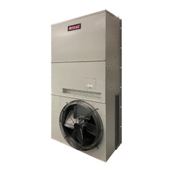
Installation & Operation Manual
3.5, 4 & 5 Ton Vertical Wall-Mount Heat Pumps
Single Stage Models:
EAA1042H • EAA1048H • EAA1060H
2-Stage Models:
EAA2042H • EAA2048H • EAA2060H
This manual may include information for options and features which may not be
included on the unit being installed. Refer to the unit data label or Model Identification
to determine which features and options this unit is equipped with.
INSTALLER: Affix the instructions on the inside of the building adjacent to the thermostat.
END USER: Retain this manual for future reference.
A Division of the AIRXCEL
P.O. Box 400 • Cordele, Georgia 31010 • 156 Seedling Drive • Cordele, Georgia 31015
E-mail: marvairsales@airxcel.com • Internet: www.Marvair.com
The most current version of this manual can be found at www.Marvair.com.
An AirX Climate Solutions Brand
IMPORTANT
Manufactured By:
(229) 273-3636 • Fax (229) 273-5154
Heat Pump Product Manual
Vertical Wall-Mount Heat Pumps
Commercial Group
®
Eubank Wall Mount Heat Pump I&O Manual
11/2021 New
Advertisement
Table of Contents
Troubleshooting

Related Manuals for Eubank EAA1042H


Summary of Contents for Eubank EAA1042H
- Page 1 P.O. Box 400 • Cordele, Georgia 31010 • 156 Seedling Drive • Cordele, Georgia 31015 (229) 273-3636 • Fax (229) 273-5154 E-mail: marvairsales@airxcel.com • Internet: www.Marvair.com The most current version of this manual can be found at www.Marvair.com. Eubank Wall Mount Heat Pump I&O Manual 11/2021 New...
- Page 2 How To Use This Manual This manual is intended to be a comprehensive guide to the installation of the Eubank EAA family of vertical packaged ® heat pumps. It contains installation, troubleshooting, maintenance, warranty, and application information. The information contained in this manual is to be used by the installer as a guide only. This manual does not supersede or circumvent any applicable national or local codes.
-
Page 3: Table Of Contents
4.1 Overview ............................... 30 4.2 Failure Symptoms Guide ........................31 4.3 Compressor Troubleshooting ........................ 32 4.4 Electric Heat Control ..........................33 Chapter 5 - Electrical Schematics 5.1 Electrical Schematics ..........................34 Eubank Wall Mount Heat Pump I&O Manual 11/2021 New... - Page 4 Table 3 Filter Sizes ..........................7 Table 4 Refrigerant Charge........................7 Table 5 Ambient Temperature Operating Ranges .................. 7 Table 6 Minimum Clearances ......................17 Table 7 Voltage Limitations ........................17 Eubank Wall Mount Heat Pump I&O Manual 11/2021 New...
-
Page 5: General Description
All internal wiring is complete. Eubank EAA heat pump models are available in a wide variety of styles and configurations to meet the various ventilation and cooling requirements. For school classrooms, models are available to comply with the ASHRAE 62-1999 standard, “Ventilation for Acceptable Indoor Air Quality.”... -
Page 6: Model Identification
30 Special Variation $ = Special Configuration Not Covered by Model Nomenclature Note: Not all options are available with all configurations. Contact your Eubank sales representative for configuration details and feature compatibility. Eubank Wall Mount Heat Pump I&O Manual 11/2021 New... -
Page 7: Air Flow, Weights, Filter Sizes, Refrigerant Charges And Ambient Operating Ranges
1.5 General Operation Refrigerant Cycle Eubank heat pumps use R-410A refrigerant in a conventional vapor-compression refrigeration cycle to transfer heat. In the cooling mode, a double blower assembly blows indoor air across the evaporator (indoor coil). Liquid refrigerant passing through the evaporator is boiled into gas by heat removed from the air. - Page 8 HVAC is in economizer mode verses mechanical cooling mode. This feedback allows the CommStat 4 to initiate the forced cooling feature to override economizer cooling and force mechanical cooling. When used with minimum position potentiometer (optional), the Eubank economizer can meet requirements of ASHRAE Std. 62.
-
Page 9: Controls - Standard - Pc Board
The heat pump is factory wired to be normally open. Eubank Wall Mount Heat Pump I&O Manual 11/2021 New... - Page 10 Electric Heat During Defrost (EHDD) and “No” selected for the S-Circuit, the electric heat (EH) output will be energized during a defrost cycle to supply heat while the coil defrosts. Eubank Wall Mount Heat Pump I&O Manual 11/2021 New...
- Page 11 LPS fault, and initiate the 3 minute anti-short cycle timer. If two LPS faults occur within a one hour period, the control will enter a LPS lockout condition Eubank Wall Mount Heat Pump I&O Manual 11/2021 New...
- Page 12 HPS High Pressure switch terminals are the high pressure switch input. LPS Loss of Charge switch terminals are the loss of charge switch input. DS The DS terminals are the defrost sensor input. Eubank Wall Mount Heat Pump I&O Manual 11/2021 New...
-
Page 13: Options
Adjustable Outdoor Thermostat Will not allow electric resistance heat to be energized unless the outdoor temperature is below the desired set point. Field or factory installed. Available on all Eubank units. P/N 93934 Single Point Feed When multiple internal disconnects are used, single point feed permits only one field power supply to heat pump. -
Page 14: Economizer Opertation And Components
(i.e., economizer cooling). If the outdoor ambient is too hot or humid, the sensor will place the actuator in the closed or minimum open position and activate mechanical cooling. The compressor is locked out during the economizer cooling mode. Eubank Wall Mount Heat Pump I&O Manual 11/2021 New... -
Page 15: Figure 2 Enthalpy Sensor Temperature Control Points
The thermistor senses the air temperature entering the structure, and provides a signal to the economizer controller for modulating the position of the damper. Nominal resistance of the sensor at 77°F is 3000 ohms. Eubank Wall Mount Heat Pump I&O Manual 11/2021 New... -
Page 16: Chapter 2 - Installation
C) The unit exhausts air. Be sure that the airflow is not impeded by shrubbery or other obstructions. D) When installing multiple units, please note the recommended clearances noted in Table 4. Eubank Wall Mount Heat Pump I&O Manual 11/2021 New... -
Page 17: Installation Materials
2.3 Installation Materials Installation Kits Eubank EAA Heat Pumps have built-in mounting flanges that function as side brackets. All models require and are shipped with a bottom mounting bracket. On units with the "N" ventilation option, there is a fresh air hood factory installed behind the lower front panel. - Page 18 1” (25mm) thick filter. The return filter grille is not recommended for use with the EAA heat pumps with economizers. Additional Items Needed: Additional hardware and miscellaneous supplies (not furnished by Eubank ) are needed for installation. ®...
-
Page 19: Porting And Duct Work
Applications using duct work should be designed and installed in accordance with all applicable safety codes and standards. Eubank strongly recommends referring to the current edition of the National Fire Protection Association Standards 90A and 90B before designing and installing duct work. The duct system must be engineered to insure sufficient air flow through the unit to prevent over-heating of the heater element. -
Page 20: Fresh Air Hood Adjustment
For example, on wooden structures, use 3/8 x 2-1/2 inch all-thread lag screws. The screws must penetrate the center of the wall stud. Drill a pilot hole in the stud to prevent it from splitting. Eubank Wall Mount Heat Pump I&O Manual 11/2021 New... -
Page 21: Mounting The Unit
10. To minimize sound transmission, a latex based, insulating foam seal may be applied between the duct extensions and the frame for the wall openings. NOTE: DO NOT USE THE FOAM ON ANY UNITS WITH ELECTRIC RESISTANT HEATERS. Eubank Wall Mount Heat Pump I&O Manual 11/2021 New... -
Page 22: Electrical Connections
An alternate method of verification for self contained system with small Eubank Wall Mount Heat Pump I&O Manual 11/2021 New... - Page 23 Terminals 8 & 10 on the Eubank with economizer can be connected to a normally closed smoke alarm or fire stat to cause equipment shutdown when the circuit is opened. (Remove factory jumper).
-
Page 24: Figure 5A Humidity Control Wiring Detail
Figure 5a - Humidity Control Wiring Detail - Heat Pumps Figure 5b - Thermostat Connection Diagram Eubank Wall Mount Heat Pump I&O Manual 11/2021 New... -
Page 25: Chapter 3 - Start-Up
Various thermostats can be used to control the heat pump. The thermostat may have a fan switch with an Automatic and On positions, a system switch with Heat, Cool, and Off positions, and an emergency heat position with lights. The spec sheets have detailed description of the various Eubank ®... -
Page 26: Check-Out Of Heating Cycle
2. Raise the heating set point temperature to a setting which is higher than the room temperature. The fan and compressor should cycle on after time delay (standard on Eubank heat pumps with an economizer and optional on all other Eubank units) has cycled. -
Page 27: Figure 6 Temperature Sensor Wires - Modulating Hgr Valve
68ºF and no higher than 78ºF. Allow the refrigerant system to stabilize for at least five minutes and adjust the temperature as desired. Adjustment Knob Positive (Red) Negative (Black) Figure 7 - Desired Temperature Set Point Eubank Wall Mount Heat Pump I&O Manual 11/2021 New... -
Page 28: Ventilation System Set Up
3.4 Ventilation System Set-Up: Manual Fresh Air System (Configuration N). This is the standard ventilation system in Eubank heat pumps. Fresh air ventilation by means of a damper can provide up to 15% of rated air flow of outside air. The damper has four positions corresponding to 0, 5, 10 and 15% of rated air flow of outside air. -
Page 29: Figure 9 Damper Air Path
The motorized damper, Configuration B, can be controlled by an optional relay that allows additional external control with a choice of 24, 120 or 240V coils to regulate fresh air ventilation in response to a control located remote from the Eubank heat pump. Eubank Wall Mount Heat Pump I&O Manual... -
Page 30: Chapter 4 - Troubleshooting
Please read the Chapter 1 for basic information about the unit. Eubank Heat Pumps are thoroughly tested before they are shipped from the factory. However, it is possible that a defect may escape undetected, or damage may have occurred during transportation. However, the great majority of problems result from installation errors. -
Page 31: Failure Symptoms Guide
Test components (especially the compressor) for shorts. 4. Excessively high or low supply volt- 4. Note voltage range limitations specific to the age or phase loss (3ø only). compressor troubleshooting section. Eubank Wall Mount Heat Pump I&O Manual 11/2021 New... -
Page 32: Compressor Troubleshooting
A short circuit at a high voltages indicates a motor defect. Do not do this test under vacuum. 4. On single phase models, check the capacitor by substitution. Eubank Wall Mount Heat Pump I&O Manual 11/2021 New... -
Page 33: Electric Heat Control
This switch would typically open if both elements of the dual thermal cut-out switches failed. Eubank Wall Mount Heat Pump I&O Manual 11/2021 New... -
Page 34: Chapter 5 - Electrical Schematics
The indoor evaporator fan motor is cycled by the blower timed delay relay. See Figure 9. Due to the large number of variations and options available for the Eubank heat pumps, it is not practical to include every possible wiring schematic in this manual. The following schematics are typical. Included in each heat pump is the electrical schematic for that unit. -
Page 35: Figure 11A Typical 1Ø Electrical Schematic Diagram Heat Pump With Manual Outside Air Damper
Figure 11a - Typical 1ø Electrical Schematic Diagram Heat Pump (Models EAA) with Manual Outside Air Damper Eubank Wall Mount Heat Pump I&O Manual 11/2021 New... -
Page 36: Figure 11B Typical 208/230V. 3Ø Heat Pump Electrical Schematic Diagram
Figure 11b - Typical 208/230v. 3ø Electrical Schematic Diagram Heat Pump (Models EAA) Eubank Wall Mount Heat Pump I&O Manual 11/2021 New... -
Page 37: Figure 11C Typical 460V. 3Ø Heat Pump Electrical Schematic Diagram, With Pc Control Board
Figure 11c, Typical 460v. 3ø Electrical Schematic Diagram Heat Pumps, Models EAA, with the PC Control Board Eubank Wall Mount Heat Pump I&O Manual 11/2021 New... -
Page 38: Scheduled Maintenance
Regularly check the primary and secondary condensate drains. The secondary drain has a stand pipe. An obstruction will force water to dump into the middle of the unit and drain out the sides of the Eubank Heat Pump, causing discoloration of the side panels. If discoloration is noted, service the drains. -
Page 39: Chapter 7 - Warranty Information 7.1 Standard Product Warranty
Marvair, ICE, Eubank Products 90 Days w/Flat Rate Labor (See Marvair, ICE, Eubank Flat Rate Labor Guidelines) 1 Year Parts 5 Years Compressor If any part of your Marvair, Inc. unit fails within 90 days of the commencement of the warranty, Marvair, Inc. will furnish without charge, EX Works, Cordele, Georgia, the required replacement part and pay for the labor to replace the part in accordance with the Marvair, Inc. -
Page 40: Appendix A - Installation Instructions Of Field Installed Electric Heat
The 1" (25.4 mm) clearance must extend on all sides of the supply duct for the first 3 feet (1 meter) from the unit. IMPORTANT: Eubank requires a minimum of 1" (25.4 mm) from the surface of any supply ducts to combustible material for the first 3 feet (1 meter) of the duct. - Page 41 15. Place the wiring diagram provided with the heater kit inside the zip lock bag which is affixed to the back side of the control box cover. 16. Replace the control box cover, the bottom front cover and the top front panel. Eubank Wall Mount Heat Pump I&O Manual 11/2021 New...
- Page 42 Eubank Wall Mount Heat Pump I&O Manual 11/2021 New...
-
Page 43: Appendix B: Heat Pump Start-Up - Commissioning Checklist
Is the correct filter(s) in place and clean? ................. ❒Yes ❒No Refrigerant Piping Is there any evidence of refrigerant leaks (oil leaks, etc.)? ..........❒Yes ❒No If leaks are found, report them to Eubank Warranty Service Dept. Eubank Wall Mount Heat Pump I&O Manual 11/2021 New... - Page 44 If using a standard thermostat, Set the Control to ON, Mode to Cooling, Fan to Auto (other controls, set appropriately for cooling mode). Note: The reversing valve (Eubank Heat Pumps) is energized for “Cooling”. The “O” signal from the thermostat is Required.
- Page 45 719 / 3 = 239.7 Volts (Average Voltage) 239.7 (Average Voltage) – 235 (Maximum Deviation) = 4.7 (Deviation Difference) (4.7 x 100)/239.7 = 1.95% Voltage Imbalance (Less than 2% is acceptable) Eubank Wall Mount Heat Pump I&O Manual 11/2021 New...
- Page 46 Is the Compressor On? ...................... ❒Yes ❒No Is the Condenser Fan (CFM) On? ..................❒Yes ❒No Is the Heater Off? (Clamp an AmpProbe on one leg of the heater contactor to verify) ... ❒Yes ❒No Eubank Wall Mount Heat Pump I&O Manual 11/2021 New...
- Page 47 Return Air Temperature (RAT) wb (used to calculate RH% of Return Air) ºF Supply Air Temperature (SAT) db (Acceptable Range 55ºF (+/- 3ºF) ºF Return Air Temperature (SAT) wb (used to calculate RH% of Supply Air) ºF Eubank Wall Mount Heat Pump I&O Manual 11/2021 New...
- Page 48 If using a standard thermostat, Set the Control to ON, Mode to Heat, Fan to Auto (other controls, set appropriately for heating mode). Note: The reversing valve (Eubank Heat Pumps) is de-energized for “Cooling”. The “O” signal from the thermostat is Not Required.
- Page 49 Mechanical Heat Lockout, start heating with Only Electric heat. Notice: system did not turn off. “Mechanical Heat” turned Off and “Electric Heat” turned On. Note: The “S” Circuit (Eubank Heat Pump control board) must be set to “Yes”, to allow Mechanical Heat Lockout.
- Page 50 ** Please provide a description of the issue in the Notes section below and if you need help, call: Eubank Technical and Warranty Support: (888) 726-2734 This number is manned M-F, 8:00am to 5:00pm eastern. Technical support calls will be returned M-F, 5:00pm to 8:00pm eastern.
- Page 51 Notes: ____________________________________________________________________________________ ____________________________________________________________________________________ ____________________________________________________________________________________ ____________________________________________________________________________________ ____________________________________________________________________________________ ____________________________________________________________________________________ ____________________________________________________________________________________ ____________________________________________________________________________________ ____________________________________________________________________________________ ____________________________________________________________________________________ ____________________________________________________________________________________ ____________________________________________________________________________________ ____________________________________________________________________________________ ____________________________________________________________________________________ ____________________________________________________________________________________ ____________________________________________________________________________________ ____________________________________________________________________________________ ____________________________________________________________________________________ ____________________________________________________________________________________ ____________________________________________________________________________________ ____________________________________________________________________________________ ____________________________________________________________________________________ ____________________________________________________________________________________ ____________________________________________________________________________________ ____________________________________________________________________________________ Eubank Wall Mount Heat Pump I&O Manual 11/2021 New...
Need help?
Do you have a question about the EAA1042H and is the answer not in the manual?
Questions and answers