Sign In
Upload
Manuals
Brands
Eubank Manuals
Heat Pump
EAA1060H
Eubank EAA1060H Manuals
Manuals and User Guides for Eubank EAA1060H. We have
1
Eubank EAA1060H manual available for free PDF download: Installation & Operation Manual
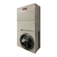
Eubank EAA1060H Installation & Operation Manual (51 pages)
Vertical Wall-Mount Heat Pumps
Brand:
Eubank
| Category:
Heat Pump
| Size: 2 MB
Table of Contents
Table of Contents
3
General Description
5
Serial Number Date Code
5
Model Identification
6
Air Flow, Weights, Filter Sizes, Refrigerant Charges and Ambient Operating Ranges
7
CFM @ External Static Pressure
7
General Operation
7
Table 2 Ship Weight
7
Table 3 Filter Sizes
7
Table 4 Refrigerant Charge
7
Table 5 Ambient Temperature Operating Ranges
7
Controls - Standard - PC Board
9
Options
13
PC Control Board
13
Economizer Opertation and Components
14
Figure 2 Enthalpy Sensor Temperature Control Points
15
Chapter 2 - Installation
16
Equipment Inspection
16
Installation Requirements
16
Installation Materials
17
Table 6 Minimum Clearances
17
Table 7 Voltage Limitations
17
Porting and Duct Work
19
Fresh Air Hood Adjustment
20
Bracket Installation
20
Figure 3 Fresh Air Hood Damper
20
Mounting the Unit
21
Figure 4 Heat Pump Wall Mounting Detail
21
Electrical Connections
22
Figure 5A Humidity Control Wiring Detail
24
Figure 5B Thermostat Connection Diagram
24
Chapter 3 - Start-Up
25
Check-Out of Cooling Cycle
25
Check-Out of Heating Cycle
26
Discharge Air Adjustment for Modulating Hot Gas Reheat (HGR) Valve
26
Figure 6 Temperature Sensor Wires - Modulating HGR Valve
27
Figure 7 Desired Temperature Set Point - Modulating HGR Valve
27
Ventilation System Set up
28
Figure 8 Damper Adjustment
28
Figure 9 Damper Air Path
29
Chapter 4 - Troubleshooting
30
Overview
30
Failure Symptoms Guide
31
Compressor Troubleshooting
32
Electric Heat Control
33
Figure 10 Typical Configuration for Single Element Heater
33
Chapter 5 - Electrical Schematics
34
Electrical Schematics
34
Figure 11A Typical 1Ø Electrical Schematic Diagram Heat Pump with Manual Outside Air Damper
35
Figure 11B Typical 208/230V. 3Ø Heat Pump Electrical Schematic Diagram
36
Figure 11C Typical 460V. 3Ø Heat Pump Electrical Schematic Diagram, with PC Control Board
37
Scheduled Maintenance
38
Chapter 7 - Warranty Information 7.1 Standard Product Warranty
39
Appendix A - Installation Instructions of Field Installed Electric Heat
40
APPENDIX B: Heat Pump Start-Up - Commissioning Checklist
43
Advertisement
Advertisement
Related Products
Eubank EAA1042H
Eubank EAA1048H
Eubank EAA2042H
Eubank EAA2048H
Eubank EAA2060H
Eubank EAA1060A
Eubank EAA1060
Eubank EAA1020A
Eubank EAA1024
Eubank EAA1042
Eubank Categories
Air Conditioner
Heat Pump
More Eubank Manuals
Login
Sign In
OR
Sign in with Facebook
Sign in with Google
Upload manual
Upload from disk
Upload from URL