
Related Manuals for Eubank H SERIES


Summary of Contents for Eubank H SERIES
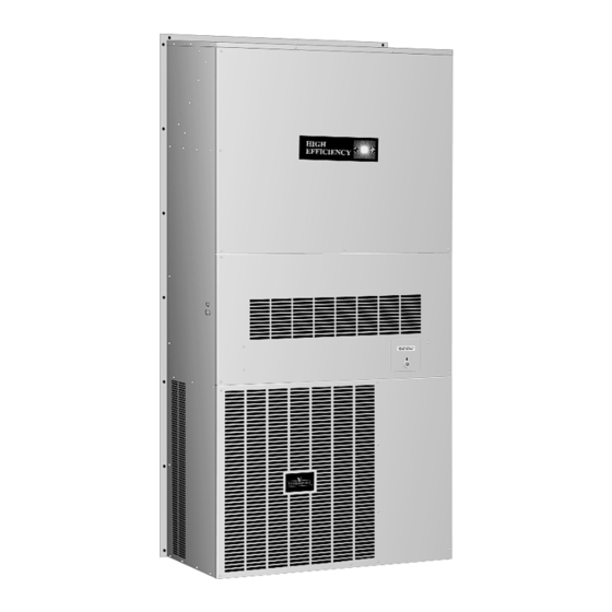
- Page 1 Installation, Operation and Maintenance H SERIES Wallmount Heat Pumps R410A Series REV. 9/23/13 678629-H-C REV. 11/1/09 678629-H-B...
-
Page 2: Maintenance
A. Turn the power to the unit off at the unit disconnect. The A thorough inspection of the shipping container should be made disconnect is located on the front of the H Series unit behind immediately upon receiving your unit. Look for any punctures or a small access door. - Page 3 C. UNIT PREPARATION A. Follow steps A and B at left INSULATION 1. The H Series model units have top rain flashing built onto the “TO CHANGE SYSTEM FILTER”. unit. The bottom-mounting flange for all models is shipped separately and in place. (Refer to “Section J. Unit Installation”...
-
Page 4: Electrical Hook-Up
See Figure 1 for reference. Refer to wiring diagrams on for connection details. STAGING OF ELECTRIC HEAT All H Series units with electric heat assemblies are wired for two- FIGURE 1 stage heat in normal operation. Units over 10 kW resistance heat also have an additional stage for emergency heat. -
Page 5: Condensate Drain
After the defrost thermostat reaches 65°F ± 5°F, the defrost cycle will end. The control will not allow the defrost to continue longer than 10 Electric heat is an option on H Series units and can be field-installed minutes. on either single- or three-phase models. - Page 6 EXPLODED PARTS DRAWING — 24 / 30 / 36...
- Page 7 EXPLODED PARTS DRAWING — 42 / 48 / 60...
- Page 8 REPLACEABLE PARTS LIST- H SERIES WALLMOUNT HEAT PUMPS PART NUMBER DESCRIPTION H424B1 H430B1 H430B3 H436B1 H436B3 H436B4 H448B1 H448B3 H448B4 H460B1 H460B3 H460B4 COMP-BZP24-001 ZP24K5EPFV130 COMP-BZP28-001 ZP28K5EPFV130 COMP-BZP28-003 ZP28K5ETF5130 COMP-BZP34-001 ZP34K5EPFV130 COMP-BZP34-003 ZP34K5ETF5130 COMP-BZP34-004 ZP34K5ETFD130 COMP-BZP44-001 ZP44K5EPFV130 COMP-BZP44-003 ZP44K5ETF5130 COMP-BZP44-004 ZP44K5ETFD130...
- Page 9 REPLACEABLE PARTS LIST- H SERIES WALLMOUNT HEAT PUMPS PART NUMBER DESCRIPTION H424B1 H430B1 H430B3 H436B1 H436B3 H436B4 H448B1 H448B3 H448B4 H460B1 H460B3 H460B4 2023-5010 TOP FRONT PANEL H48-60 COMP-BZP24-001 ZP24K5EPFV130 2021-5011 MIDDLE FRONT PANEL (no fresh air) H18-24 COMP-BZP28-001 ZP28K5EPFV130...
- Page 10 H Series Heat Pumps Electrical Data SINGLE-FIELD CIRCUIT DUAL-FIELD CIRCUIT NO. OF MAX. OVER FIELD Model No. & MIN. VOLT/ FIELD CURRENT POWER GROUND Electric Heater [2] MAX. OVER [3, 4, 5] GROUND CIRCUIT MIN. CIRCUIT PHASE POWER PROTECTION WIRE SIZE...
- Page 11 H pg 11.indd 1 9/23/13 9:22 AM...
- Page 12 H pg 12.indd 1 9/23/13 9:19 AM...
- Page 13 H pg 13.indd 1 9/23/13 9:20 AM...
- Page 14 UNIT DIMENSIONS – NOTES – MODEL A 30/36 48/60 A - FLANGE WIDTH B - UNIT WIDTH 1" SUPPLY AIR SERVICE OPENING " DOOR FILTER ACCESS DOOR " " RETURN AIR OPENING DISCONNECT " OPENING FILTER GRILL IS " LARGER THAN “I” & “E” "...
- Page 16 The information in this manual supersedes and replaces the previous instruction/operation manual 678629-V with regards to V Series wallmount products. Illustrations, part numbers and others cover the general appearance of the units at the time of publication and the manufacturer reserves the right to make changes in design and construction at any time without notice. For replacement parts contact: National Coil Company 1998 FM 2011...
Need help?
Do you have a question about the H SERIES and is the answer not in the manual?
Questions and answers