Table of Contents
Advertisement
Quick Links
Installation & Operation Manual
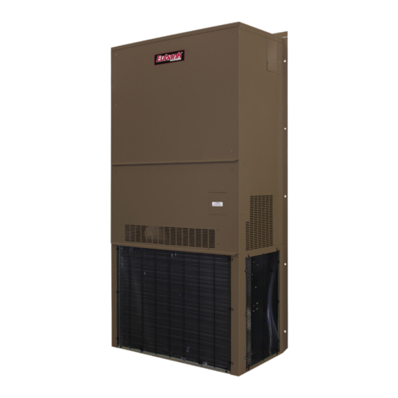
11 EER Vertical Wall-Mount Heat Pumps
7AA1024H-1030H-1036H-1042H-1048H-1060H
(Single Stage Compressor)
7AA2024H-2030H-2036H-2042H-2048H-2060H
(2-Stage Compressor)
(Includes units with the GreenWheel
and GreenCube
This manual may include information for options and features which may not be
included on the unit being installed. Refer to the unit data label or Model Identification
to determine which features and options this unit is equipped with.
INSTALLER: Affix the instructions on the inside of the building adjacent to the thermostat.
END USER: Retain this manual for future reference.
P.O. Box 400 • Cordele, Georgia 31010 • 156 Seedling Drive • Cordele, Georgia 31015
E-mail: eubanksales@airxcs.com • Internet: www.EubankWallMount.com
The most current version of this manual can be found at www.EubankWallMount.com.
MODELS:
®
ERV)
®
IMPORTANT
Manufactured By:
Eubank, An AirX Climate Solutions Brand
(229) 273-3636 • Fax (229) 273-5154
Eubank 7AA1024H-1060H & 7AA2024H-2060H I&O Manual 06/2023 Rev.4
Heat Pump Product Manual
Vertical Wall-Mount Heat Pumps
with Front Control Box Panel
ERV,
Advertisement
Table of Contents
Troubleshooting

Related Manuals for Eubank 7AA1024H-1030H-1036H-1042H-1048H-1060H


Summary of Contents for Eubank 7AA1024H-1030H-1036H-1042H-1048H-1060H
- Page 1 P.O. Box 400 • Cordele, Georgia 31010 • 156 Seedling Drive • Cordele, Georgia 31015 (229) 273-3636 • Fax (229) 273-5154 E-mail: eubanksales@airxcs.com • Internet: www.EubankWallMount.com The most current version of this manual can be found at www.EubankWallMount.com. Eubank 7AA1024H-1060H & 7AA2024H-2060H I&O Manual 06/2023 Rev.4...
- Page 2 How To Use This Manual This manual is intended to be a comprehensive guide to the installation of Eubank wall mount vertical packaged heat ® pumps. It contains installation, troubleshooting, maintenance, warranty, and application information. The information contained in this manual is to be used by the installer as a guide only. This manual does not supersede or circumvent any applicable national or local codes.
-
Page 3: Table Of Contents
4.4 Ventilation System Set Up ........................41 Chapter 5 - Troubleshooting 5.1 Overview ............................... 44 5.2 Failure Symptoms Guide ........................45 5.3 Compressor Troubleshooting ........................ 46 5.4 Electric Heat Control ..........................46 Eubank 7AA1024H-1060H & 7AA2024H-2060H I&O Manual 06/2023 Rev.4... - Page 4 Fresh Air Hood Damper ......................32 Figure 4 Heat Pump Wall Mounting Detail ................... 33 Figure 5a Humidistat Wiring to a Eubank Heat Pump with Reheat ............36 Figure 5b Thermostat Connection Diagram .................... 36 Figure 5c CommStat 4 Wiring Diagram ....................37 Figure 6 Temperature Sensor Wires - Modulating HGR Valve ............
-
Page 5: Chapter 1 Description & Specifications
Units). All Eubank heat pumps meet or exceed the efficiency requirements of ANSI/ASHRAE/IESNA 90.1.2016. All heat pump models are listed by ETL and tested to UL standard 1995, 4th Edition. Eubank heat pumps are commercial units and are not intended for use in residential applications. -
Page 6: Model Identification
$ = Special Configuration Not Covered by $ = Special Model Nomenclature Note: Not all options are available with all configurations. Contact your Eubank sales representative for configuration details and feature compatibility. Eubank 7AA1024H-1060H & 7AA2024H-2060H I&O Manual 06/2023 Rev.4... -
Page 7: Serial Number Date Code
927 x 559 x 25 80139 7AA1030H/1036H/1042H & Filter 7AA2036H/2042H Intake Air w/GreenWheel ERV 14 x 14 x 1 356 x 356 x 25 80192 Filter* *Units with the GreenWheel ERV Table 3. Filter Sizes Eubank 7AA1024H-1060H & 7AA2024H-2060H I&O Manual 06/2023 Rev.4... -
Page 8: General Operation
1.5 General Operation Refrigerant Cycle Eubank heat pumps use R-410A refrigerant in a conventional vapor-compression refrigeration cycle to transfer heat. In the cooling mode, a double blower assembly blows indoor air across the evaporator (indoor coil). Liquid refrigerant passing through the evaporator is boiled into gas by heat removed from the air. - Page 9 Configuration “N”: Manual Fresh Air Damper (Standard) Barometric damper capable of up to 15% of the air conditioner’s total rated airflow of outside air; field adjustable, no pressure relief. Eubank 7AA1024H-1060H & 7AA2024H-2060H I&O Manual 06/2023 Rev.4...
- Page 10 This assures the classroom temperature is maintained as first priority and humidity control is second. The humidity controller or BAS control is required for proper operation of the HGR coil. Eubank 7AA1024H-1060H & 7AA2024H-2060H I&O Manual 06/2023 Rev.4...
-
Page 11: Chapter 2 Electronic Control Board
Lockout contacts are also provided along with the alarms being transferred via Modbus. This chapter provides the necessary information for installing and operating the Eubank PCB. The diagram below identifies the inputs, outputs and connections for the Eubank PCB. See I/O table. -
Page 12: Installation And Replacement
Low Pressure Lockout Compressor Circuit 1 LP-2 Low Pressure Lockout Compressor Circuit 2 HP-1 High Pressure Lockout Compressor Circuit 1 HP-2 High Pressure Lockout Compressor Circuit 2 Low Voltage "Brownout" 16VAC or Less for 10 Minutes Eubank 7AA1024H-1060H & 7AA2024H-2060H I&O Manual 06/2023 Rev.4... - Page 13 Available Baud Rates 9.6 = 9600, 19 = 19200 Modbus timeout 21916 Communications Timeout in minutes Test Y, n When set to “Y” all timers are reduced for testing SW version number Displays the current version software Eubank 7AA1024H-1060H & 7AA2024H-2060H I&O Manual 06/2023 Rev.4...
- Page 14 The selections for the SCKT Set are Y (yes) or N (no). When set to N (no, Default) the electric heat will be allowed to operate with the compressor in heat-pump mode upon a call Eubank 7AA1024H-1060H & 7AA2024H-2060H I&O Manual 06/2023 Rev.4...
- Page 15 17. Dehum Speed: This is an independent setting for the speed at which the Indoor blower will operate upon a request for HUM (Dehumidification) via Digital Input or Modbus. The default setting for Eubank 7AA1024H-1060H & 7AA2024H-2060H I&O Manual 06/2023 Rev.4...
-
Page 16: Operation
Operation Power The Eubank PCB requires 24 VAC to operate. When the board is sufficiently powered, the “PWR” status light on the PCB illuminates “Green.” When the power supply voltage is 16vac or less for 10 seconds the control board will de-energize all outputs. This is considered a voltage brownout (low voltage) condition and the display of the control board will show “03”... - Page 17 2. Normal Operating Mode describes a mode in which there are no active faults which would interrupt the operation of the system. Eubank 7AA1024H-1060H & 7AA2024H-2060H I&O Manual 06/2023 Rev.4...
- Page 18 Stage 1 Cooling (1 Staged Compressor) CC1 (Partial Capacity) Stage 2 Cooling (2 Fixed Compres-sors) Y1 + Y2 CC1 + CC2 (Full Capacity) Stage 2 Cooling (2 Staged Compres-sors) Y1 + Y2 CC1 + CC2 (Full Capacity) Eubank 7AA1024H-1060H & 7AA2024H-2060H I&O Manual 06/2023 Rev.4...
- Page 19 “Stage1 Cooling” Y1 + O signal via Digital input or Modbus), energizes the Reversing Valve Output (RV) and Compressor 1 Relay Output (CC1) on the PCB. The controller provides a continuous control signal associated to the Indoor Fan Motor, that is proportional Eubank 7AA1024H-1060H & 7AA2024H-2060H I&O Manual 06/2023 Rev.4...
- Page 20 Note: Selecting N=No in configuration setting 12 will disable economizer operation. DANGER Sever hazard. The economizer contains moving parts capable of causing serious injury or death. Disconnect power before removing the covering panel. Eubank 7AA1024H-1060H & 7AA2024H-2060H I&O Manual 06/2023 Rev.4...
-
Page 21: Enthalpy Sensor Temperature Control Points
63°F. This setpoint can be adjusted in 1F increments from 20F to 105F in the control board configuration menu setting 14. Example of the dry bulb sensor is shown below. Note: Selecting N=No in configuration setting 12 will disable economizer operation. Eubank 7AA1024H-1060H & 7AA2024H-2060H I&O Manual 06/2023 Rev.4... -
Page 22: Figure 2 Dry Bulb Sensor
(no staging). The Heater will remain on until the Heating setpoint is satisfied and the request is dropped. Once the heating setpoint is satisfied, the Indoor motor continues to run based Eubank 7AA1024H-1060H & 7AA2024H-2060H I&O Manual 06/2023 Rev.4... - Page 23 Modbus), the system will run the Indoor Motor for 10 seconds prior to energizing the Heater Output. The Indoor Motor will operate at the “W2” speed setting on the board or via Modbus. Eubank 7AA1024H-1060H & 7AA2024H-2060H I&O Manual 06/2023 Rev.4...
- Page 24 The indoor fan motor will operate at the “Dehum” speed setting on the board or via Modbus. The indoor fan remains on continuously but the outdoor fan modulates based on liquid line temperature. The Fan Cycle Eubank 7AA1024H-1060H & 7AA2024H-2060H I&O Manual 06/2023 Rev.4...
- Page 25 The system will continue to lockout until the problem is rectified. Eubank 7AA1024H-1060H & 7AA2024H-2060H I&O Manual 06/2023 Rev.4...
- Page 26 Outdoor Fan Motor on and off to maintain the head-pressure of the system, the OFR output is only used on systems with PSC out door motor and Fan Cycle Switch (FCC) only. Eubank 7AA1024H-1060H & 7AA2024H-2060H I&O Manual 06/2023 Rev.4...
- Page 27 8.0 Smoke / Fire Shutdown 8.1 System Shutdown Contact Wiring – Add Normally Closed Dry contacts as shown for immediate shutdown of HVAC upon contacts opening. Eubank 7AA1024H-1060H & 7AA2024H-2060H I&O Manual 06/2023 Rev.4...
-
Page 28: Chapter 3 Installation
C) The unit exhausts air. Be sure that the airflow is not impeded by shrubbery or other obstructions. D) When installing multiple units, please note the recommended clearances noted in Table 4. 5. Airflow Requirements: Eubank 7AA1024H-1060H & 7AA2024H-2060H I&O Manual 06/2023 Rev.4... -
Page 29: Installation Materials
3.3 Installation Materials Installation Kits Eubank Heat Pumps have built-in mounting flanges that function as side brackets. All models require and are shipped with a bottom mounting bracket. On units with the "N" ventilation option, there is a fresh air hood factory installed behind the lower front panel. - Page 30 80679 30" x 16" Aluminum Return Grille for 7AA1030H-1060H Return Air Filter Grille 80672 28" x 14" Return Air Filter Grille. Required for use with the 7AA1024H units with the Greenwheel ERV Eubank 7AA1024H-1060H & 7AA2024H-2060H I&O Manual 06/2023 Rev.4...
-
Page 31: Porting And Duct Work
Additional Items Needed: Additional hardware and miscellaneous supplies (not furnished by Eubank ) are needed for installation. ® For example, the list below contains approximate quantities of items typically needed for mounting a unit on a wood frame wall structure with standard full length mounting bracket or flanges. Concrete or fiberglass structures have different requirements. -
Page 32: Fresh Air Hood Adjustment
(no fresh air). To provide fresh air, remove the two screws on either side of the hood and reposition as desired. Figure 3 - Fresh Air Hood Damper Adjustment Eubank 7AA1024H-1060H & 7AA2024H-2060H I&O Manual 06/2023 Rev.4... -
Page 33: Bracket Installation
7. Fasten the top flange to the wall using #10 x 1/2 inch sheet metal screws. 8. On the inside of the structure, wall sleeves must be installed in the supply and return air openings. Eubank 7AA1024H-1060H & 7AA2024H-2060H I&O Manual 06/2023 Rev.4... -
Page 34: Electrical Connections
& L3 for three phase models). CAUTION CAUTION! This system contains components that require phasing for correct rotation. Failure to observe rotation and correct on start-up will cause damage not covered by the Eubank Warranty. ® Eubank 7AA1024H-1060H & 7AA2024H-2060H I&O Manual 06/2023 Rev.4... - Page 35 Terminals 8 & 10 on the heat pump with economizer can be connected to a normally closed smoke alarm or fire stat to cause equipment shutdown when the circuit is opened. (Remove factory jumper). CAUTION The internal transformer is not designed to power other external devices. Eubank 7AA1024H-1060H & 7AA2024H-2060H I&O Manual 06/2023 Rev.4...
-
Page 36: Figure 5A Humidistat Wiring To A Eubank Heat Pump With Reheat
Figure 5a. Humidistat Wiring to a Eubank Heat Pump with Reheat. Figure 5b. Thermostat Connection Diagram Eubank 7AA1024H-1060H & 7AA2024H-2060H I&O Manual 06/2023 Rev.4... -
Page 37: Figure 5C Commstat 4 Wiring Diagram
" l " R l i t . t l A " " 1 A " " 2 n i l n i l n i l Figure 5c. CommStat 4 Wiring Diagram Eubank 7AA1024H-1060H & 7AA2024H-2060H I&O Manual 06/2023 Rev.4... -
Page 38: Chapter 4 Start Up
Various thermostats can be used to control the heat pump. The thermostat may have a fan switch with an Automatic and On positions, a system switch with Heat, Cool, and Off positions, and an emergency heat position with lights. The spec sheets have detailed description of the various Eubank ®... -
Page 39: Check-Out Of Heating Cycle
1. Place the thermostat system switch to "Auto" or "Heat" and the fan to "Auto". 2. Raise the heating set point temperature to a setting which is higher than the room temperature. The fan and compressor should cycle on after time delay (standard on Eubank heat pumps with economizer) has cycled. -
Page 40: Figure 6 Temperature Sensor Wires - Modulating Hgr Valve
(temperature). Eubank recommends 70ºF and no lower than 68ºF and no higher than 78ºF. Allow the refrigerant system to stabilize for at least five minutes and adjust the temperature as desired. -
Page 41: Ventilation System Set Up
4.4 Ventilation System Set-Up: Manual Fresh Air System (Configuration N). This is the standard ventilation system in Eubank 7AA heat pumps. Fresh air ventilation by means of a damper can provide up to 15% of rated air flow of outside air. The damper has four positions corresponding to 0, 5, 10 and 15% of rated air flow of outside air. -
Page 42: Figure 9 Damper Air Path
Measure the intake air again and adjust the speed of the blowers. Repeat as necessary to meet the fresh air requirements. b. For units with the optional variable fan speed controller for the GreenWheel ERV exhaust blower, first ® Eubank 7AA1024H-1060H & 7AA2024H-2060H I&O Manual 06/2023 Rev.4... - Page 43 GreenCube ERV assembly. Access to the exhaust air controller is through the return air grille. It is usual practice to pressurize the classroom by exhausting slightly less air than is being brought into the classroom. Eubank 7AA1024H-1060H & 7AA2024H-2060H I&O Manual 06/2023 Rev.4...
-
Page 44: Chapter 5 Troubleshooting
Chapter 5 Troubleshooting 5.1 Overview A comprehensive understanding of the operation of the Eubank Heat Pump is a prerequisite to troubleshooting. Please read the Chapter 1 for basic information about the unit. Eubank Heat Pumps are thoroughly tested before they are shipped from the factory. However, it is possible ®... -
Page 45: Failure Symptoms Guide
3. Defective heater contactor. 3. Check relay for proper operation. Replace if defective. 4. Thermostat set too low. 4. Adjust thermostat. 5. Compressor fault. 5. Reset the lock out relay at the thermostat. Eubank 7AA1024H-1060H & 7AA2024H-2060H I&O Manual 06/2023 Rev.4... -
Page 46: Compressor Troubleshooting
Do not do this test under vacuum. 4. On single phase models, check the capacitor by substitution. 5.4 Electric Heat Controls Figure 10 - Typical Configuration for Single Element Heater Eubank 7AA1024H-1060H & 7AA2024H-2060H I&O Manual 06/2023 Rev.4... - Page 47 This switch would typically open if both elements of the dual thermal cut-out switches failed. Eubank 7AA1024H-1060H & 7AA2024H-2060H I&O Manual 06/2023 Rev.4...
-
Page 48: Chapter 6 - Electrical Schematics
The indoor evaporator fan motor is cycled by the blower timed delay relay. See Figure 9. Due to the large number of variations and options available for the Eubank heat pumps, it is not practical to include every possible wiring schematic in this manual. The following schematics are typical. Included in each heat pump is the electrical schematic for that unit. -
Page 49: Figure 11A Typical 1Ø Electrical Schematic Diagram Heat Pump With Manual Outside Air Damper
Figure 11a - Typical Electrical Schematic Diagram Heat Pump Models with Manual Outside Air Damper Eubank 7AA1024H-1060H & 7AA2024H-2060H I&O Manual 06/2023 Rev.4... -
Page 50: Figure 11B Typical 208/230V. 3Ø Electrical Schematic Diagram Heat Pump
Figure 11b - Typical Electrical Schematic Diagram Heat Pump Models with Economizer Eubank 7AA1024H-1060H & 7AA2024H-2060H I&O Manual 06/2023 Rev.4... -
Page 51: Scheduled Maintenance
7.1 Scheduled Maintenance Eubank strongly recommends that the heat pump be serviced a minimum of twice a year – once prior to the heating season and once prior to the cooling season. At this time the filters, evaporator coil, condenser coil, the cabinet, and condensate drains should be serviced as described below. -
Page 52: Chapter 8 - Warranty Information
Marvair, ICE, Eubank Products 90 Days w/Flat Rate Labor (See Marvair, ICE, Eubank Flat Rate Labor Guidelines) 1 Year Parts 5 Years Compressor If any part of your Marvair, Inc. unit fails within 90 days of the commencement of the warranty, Marvair, Inc. will furnish without charge, EX Works, Cordele, Georgia, the required replacement part and pay for the labor to replace the part in accordance with the Marvair, Inc. -
Page 53: Chapter 9 Start-Up Check List
Chapter 9 Start-Up Check List Start-Up & Commissioning Form Please complete the information on this form and return to Eubank by mail or fax. The mailing address and fax number can be found at the end of the form. A. Equipment Information... - Page 54 L1 & L3 = 243 Volts = 717 / 3 = 239 Average Voltage L2 & L3 = 233 Volts 239 - 233 = 6 100 x 6/239 =2.5% Voltage Unbalance Three phase units only check fan & compressor rotation. Eubank 7AA1024H-1060H & 7AA2024H-2060H I&O Manual 06/2023 Rev.4...
- Page 55 Measured Line to Line Volts L1&L2_______V. L1&L3 ________V. L2&L3______V. (L1&L2 + L1&L3 + L2&L3)/3 = Avg. Voltage = _______________ Max. Deviation from avg. voltage = ______________volts Voltage imbalance = (100 x Max. Deviation)/avg. Voltage = ___________% Eubank 7AA1024H-1060H & 7AA2024H-2060H I&O Manual 06/2023 Rev.4...
- Page 56 Evap. Leaving Air WB Temp ________ ________ Compressor Amps (L1) ________ ________ Compressor Amps (L2) ________ ________ Compressor Amps (L3) ________ ________ Notes: __________________________________________________________________________ __________________________________________________________________________ __________________________________________________________________________ __________________________________________________________________________ __________________________________________________________________________ __________________________________________________________________________ __________________________________________________________________________ __________________________________________________________________________ __________________________________________________________________________ __________________________________________________________________________ __________________________________________________________________________ Eubank 7AA1024H-1060H & 7AA2024H-2060H I&O Manual 06/2023 Rev.4...
-
Page 57: Appendix A - Installation Instructions Of Field Installed Electric Heat
The 1" (25.4 mm) clearance must extend on all sides of the supply duct for the first 3 feet (1 meter) from the unit. IMPORTANT: Eubank requires a minimum of 1" (25.4 mm) from the surface of any supply ducts to combustible material for the first 3 feet (1 meter) of the duct. - Page 58 15. Place the wiring diagram provided with the heater kit inside the zip lock bag which is affixed to the back side of the control box cover. 16. Replace the control box cover, the bottom front cover and the top front panel. Eubank 7AA1024H-1060H & 7AA2024H-2060H I&O Manual 06/2023 Rev.4...
- Page 59 Eubank 7AA1024H-1060H & 7AA2024H-2060H I&O Manual 06/2023 Rev.4...
Need help?
Do you have a question about the 7AA1024H-1030H-1036H-1042H-1048H-1060H and is the answer not in the manual?
Questions and answers