Airzone RADIANT365 Installation Manual
Hide thumbs
Also See for RADIANT365:
- Quick installation manual (96 pages) ,
- Installation manual (60 pages) ,
- Quick installation manual (88 pages)

Related Manuals for Airzone RADIANT365


Summary of Contents for Airzone RADIANT365
- Page 1 Installation Manual RADIANT365 AZRA6CB1RAD + AZX6CM1VALR P d r a o b p il C u N e g a r e b m...
- Page 2 1-8 ZONES (AZRA6CB1RAD+ AZX6CM1VALR)
-
Page 3: Table Of Contents
Environmental policy ........................................6 System elements ........................................... 7 Airzone RadianT VALR system for radiators main board (AZRA6CB1RAD) ....................7 Airzone control module for wireless valves VALR (AZX6CM1VALR) ......................7 Airzone wireless thermostatic valve actuator VALR for radiators (AZX6AC1VALR) .................. 7 Airzone Blueface Color Thermostat Wired (AZRA6BLUEFACEC) ........................ - Page 4 Zone Parameters ........................................... 26 Production parameters ....................................... 26 Self-diagnose ............................................27 Airzone Blueface and Think thermostats (AZRA6BLUEFACEC / AZRA6THINK [C/R]) ................27 Blueface and Think Thermostats Warnings ..............................27 Blueface and Think Thermostats Errors ................................27 Airzone Lite thermostat (AZRA6LITE [C/R]) ................................32 LED Status ............................................
-
Page 5: Warnings And Environmental Policy
WARNINGS AND ENVIRONMENTAL POLICY PRECAUTIONS For your security, and to protect the devices, follow these instructions: • Do not handle the system with wet or damp hands. • Disconnect the power supply before making any connections. • Take care not to cause a short circuit in any of the system connections. ENVIRONMENTAL POLICY Do not dispose of this equipment in the household waste. -
Page 6: System Elements
Relay for SHW control through dry contact (NO). • Management of control gateways for production units. Important: An Airzone Cloud Webserver and an Airzone Blueface thermostat are required. - AZX6WEBSCLOUDC, AZX6WSCLOUDDINC and AZX6WSC5GER v.3.3.2 or later, or AZX6CCPWSCC. - AZX6WEBSCLOUDR and AZX6WSCLOUDDINR incompatible. -
Page 7: Airzone Blueface Color Thermostat Wired (Azra6Bluefacec)
AIRZONE BLUEFACE COLOR THERMOSTAT WIRED (AZRA6BLUEFACEC) Color graphic interface with capacitive screen for controlling zones in Airzone systems. Powered by main control board. Finished in steel and glass. Available in white and black. Functionalities: • Available in Spanish, English, French, Italian, German and Portuguese. -
Page 8: Webserver Airzone Cloud Ethernet/Wi-Fi Dual 2.4-5G (Azx6Webscloudc/Azx6Wsc5Ger)
• Multi-user and multi-session. • Remote management of firmware updates and errors. AIRZONE AIR TO WATER HP GATEWAY (AZX6GAW XXX) Communication gateway between Airzone system and Air to water units. Powered through the AC unit bus of the production control board (AZX6CCPWSCC). Features: •... -
Page 9: General Requirements
• Perform all the connections with total abscense of power suppliance. • In order to connect the elements of the system, use Airzone cable: shielded twisted pair cable formed by 4 wires: 2x0,22 + 2x0,5mm (AWG 20 – 4 wired). -
Page 10: Introduction
INTRODUCTION Airzone systems enable the management of Master and Zone interfaces. Master thermostats enable mode management or define the efficiency level with the Eco-Adapt function. Remember: This system only admits one Master thermostat. To distinguish a Master Interface from a Zone Interface, check the next points. -
Page 11: Assembly And Connection
Boiler control Power Airzone connection bus connectors The Airzone connection bus allows you to connect all the internal components dependent on the main board to control up to 8 zones. These are the elements that can be connected: • Blueface (AZRA6BLUEFACEC), Think (AZRA6THINKC) and Lite (AZRA6LITEC) thermostats. - Page 12 The main control board can also connect to Airzone wireless elements. These elements are associated by opening the wireless association module of the main control board. Press on SW1 and wait for the LED 19 to remain red. The wireless association module will be open during 15 minutes.
-
Page 13: Airzone Control Module For Wireless Valves Valr (Azx6Cm1Valr)
Remember: Once all the connections are made, make sure you replace the cover properly. AIRZONE CONTROL MODULE FOR WIRELESS VALVES VALR (AZX6CM1VALR) Assembly This module is mounted on DIN rail. It should be placed and mounted in accordance with the current electrotechnical regulations. -
Page 14: Connection
AIRZONE WIRELESS THERMOSTATIC VALVE ACTUATOR VALR FOR RADIATORS (AZX6AC1VALR) Assembly Airzone wireless thermostatic valve actuators are mounted on each of the valves of a heater. Check that the thermostatic valve actuator is compatible with the valve body that you are going to equip (M30 x 1.5). See... -
Page 15: Connection
Place the anti-theft rods for additional support (optional). Connection The Airzone thermostats are connected to the Airzone connection bus of the main board. Attach the wires with the terminal screws following the color code. Important: Use a suitable screwdriver to press in the locking tabs. -
Page 16: Airzone Wireless Thermostat (Azra6Thinkr / Azra6Liter)
AIRZONE WIRELESS THERMOSTAT (AZRA6THINKR / AZRA6LITER) Assembly Wireless thermostats are mounted on the wall through a support. It is recommended not to locate it more than 40 meters away from the main control board. To fix it to the wall, follow these steps: •... -
Page 17: Cloud Ethernet Airzone Production Control Board (Azx6Ccpwscc)
CLOUD ETHERNET AIRZONE PRODUCTION CONTROL BOARD (AZX6CCPWSCC) Assembly The production control board is supplied to be screwed to the wall. It should be placed and mounted in accordance with the current electrotechnical regulations. For the mounting of the main control board, follow the following steps: •... - Page 18 Remember: Once all the connections are made, make sure you replace the cover properly. Digital inputs The production control board has 4 digital inputs to externally control the Airzone systems. These inputs are configured as normally open. It is recommended to use a shielded cable to connect it.
- Page 19 Radiant Heating mode 2 pipes / 4 pipes Control Relays Mode Demand FRIO_Y CALORB_W AIRE_Y RADIANTE_Y AIRE_W RADIANTE_W Stop Cooling Radiant mode Heating Radiant mode RadianT Control Relays Mode Demand FRIO_Y CALORB_W AIRE_Y RADIANTE_Y AIRE_W RADIANTE_W Stop Cooling Radiante mode Heating Radiante mode...
-
Page 20: Configuration
Assembly The Airzone air to water gateway is integrated into the domotic bus of the Cloud Ethernet Production Control Board, (AZX6CCPWSCC). It has a 4-pin terminal. Disconnect the terminal to which you want to connect to the Webserver and fit the connector. -
Page 21: Initial Configuration
IMPORTANT: not to open more than one radio channel at the same time, it may alter the process. • Start the radio channel search, to do so, press Airzone to start the search. The controller will display the different wireless zone modules found, with the signal level of each one of them. Select the wanted module and press “Check”, the selected module will begin to “beep”... - Page 22 Set the address for each wireless valve (an address of 01-10 is automatically assigned). Associate each valve with its zone. Other settings Access the advanced settings (system address, temperature range, etc.) to change other settings or activate the basic function if you want to (see Advanced Settings, zone parameters).
-
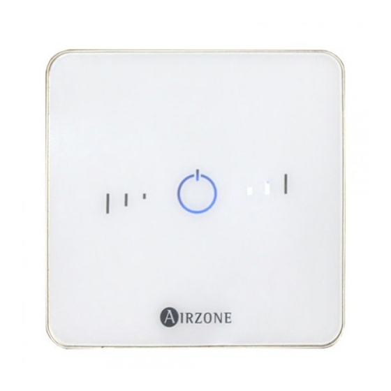
Page 23: Airzone Lite Thermostat
Think Important: Use to confirm and to return. AIRZONE LITE THERMOSTAT Zone address Select the zone associated to the thermostat pulling up the microswitch of the corresponding zone. Other settings Configure other functionalities of the LITE thermostat from the advanced configuration menu of a Blueface thermostat (see section Advanced Settings, Zone parameters). -
Page 24: Initial Configuration Evaluation
INITIAL CONFIGURATION EVALUATION Check the following aspects: • Opening-closing of the valves: Turn on the system and generate demand in all the zones. Then, switch off and on all the zones to verify the associated valves are correct. ADVANCED SETTINGS To access the advanced configuration menu of the Blueface and Think thermostats follow the following steps: Blueface Press and hold... -
Page 25: Zone Parameters
2 pipes • 4 pipes • RadianT (Recommended for RadianT365 systems) • Activation delay. It allows to set a delay time in the power on of the production unit, configurable in minutes, from 0 to 7. (Default preset to 3 minuts). -
Page 26: Self-Diagnose
Main control board status: Airzone connection bus LEDs are operating properly. Connection: Verify the polarity of the main control board and thermostat connectors. Wiring: Disconnect the terminal from the Airzone connection bus and check that the voltage between the poles (A/-) and (B/-) is about 0.65 Vdc. - Page 27 Error 1: Wireless thermostat-Main control board communication error This incident blocks the control of the zone. Check this error is not common to all thermostats. If so, verify the proper operation of the main board. To solve this incident check: Thermostat status: Check the signal range of the thermostat with the main control board through the Information parameter (see section Advanced settings, system settings) or approach the thermostat to the main control board if the thermostat recovers the communication, it is necessary to relocate it as it was out of range.
- Page 28 Check which Lite thermostat is not working properly. To solve this incident check: Connection: Check the polarity of the main control board and thermostat connectors. Wiring: Disconnect the terminal from the Airzone connection bus and check that the voltage between the poles (A/-) and (B/-) is about 0.65 Vdc.
- Page 29 Status of the control module of the radiant elements: Correctly powered. Check the polarity of the connectors of the main control board and the module. Status of the control module of the radiant elements and the main control board: Airzone connection bus LEDs are operating properly.
- Page 30 Status of the control module of the radiant elements: Correctly powered. Status of the Main Control Board: Airzone connection bus LEDs are operating properly. Connection: Check the polarity of the connectors of the CCP and the Main Control Board of the system.
-
Page 31: Airzone Lite Thermostat (Azra6Lite [C/R])
Main control board status: Airzone connection bus LEDs are operating properly. Connection: Verify the polarity of the main control board and thermostat connectors. Wiring: Disconnect the terminal from the Airzone connection bus and check that the voltage between the poles (A/-) and (B/-) is about 0.65 Vdc. -
Page 32: Led Status
Airzone RadianT VALR system for radiators main board (AZRA6CB1RAD) Airzone control module for wireless valves VALR (AZX6CM1VALR) Airzone wireless thermostatic valve actuator VALR for radiators (AZX6AC1VALR) Webserver Airzone Cloud (AZX6WSC5GER) Cloud ethernet Airzone production control board (AZX6CCPWSCC) Airzone air to water hp gateway Airzone-Daikin Altherma 3 (AZX6GAWDA2) -
Page 33: Navigation Trees
NAVIGATION TREES NAVIGATION TREE - BLUEFACE THERMOSTAT... -
Page 34: Navigation Tree - Think Thermostat
NAVIGATION TREE - THINK THERMOSTAT... - Page 35 94573 Rungis - France Cormano – Milano - Italia Teléfono: +34 900 400 445 Téléphone : +33 184 884 695 Telefono: +39 02 56814756 Fax: +34 902 400 446 Fax : +33 144 042 114 Fax: +39 02 56816158 http://www.myzone.airzonefrance.fr http://www.myzone.airzoneitalia.it http://www.myzone.airzone.es...
Need help?
Do you have a question about the RADIANT365 and is the answer not in the manual?
Questions and answers