
Related Manuals for MRC Prodigy Express2


Summary of Contents for MRC Prodigy Express2
- Page 1 MRC Prodigy Express User’s Manual Model Rectifier Corporation 360 Main Street, Suite 2 Matawan, NJ 07747 (732) 225-6360 www.modelrectifier.com Printed in USA...
-
Page 2: Table Of Contents
Setting Cab Addresses (Prodigy Express2 Cab only) � � � � � � � � � � � � � � � � � � � � � � � � � � � � � � � � � �... -
Page 3: Getting Started
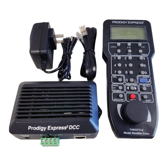
LCD Cab/Handheld with cable. The MRC Prodigy Express DCC system will enhance the enjoyment of your train layout for many years to come. Here at MRC, we pride ourselves in giving you the most advanced, reliable and easy to use DCC train controls. With up to 9,999 addresses available and use of up to 32 Cabs, you can expand your railroad empire as much as you desire. -
Page 4: Specifications And Features
Input: 15-16 volts regulated DC, 1.6 Amps. Output: DCC signal with 14.5 V amplitude, for HO and N scales Scales larger than HO may need am MRC power booster Maximum Current: 1.6 Amps Maximum number of Cabs: Use up to 32 Cabs... -
Page 5: Operation
OPERATION QUICK START Connecting to Your Layout Follow the diagram to connect the Command Station (base unit) to your layout. 1. Plug the power supply into the base unit. 2. Plug the AC line cord (110VAC, 60Hz) into a wall outlet. -
Page 6: Controlling Accessory Functions
Controlling Accessory Functions To control accessory functions F0 - F9, press 0 - 9. To control F10 - F13, press F10 - F13. To control F14 - F28, press SHIFT first and then press two digits. When F1-F12 are on, F1 - F12 will be displayed on the LCD. -
Page 7: Fast Clock (Prodigy Advance2 Cab Only)
When operating larger layouts with numerous locos and accessories being operated at the same time or when running 2-rail “O” or “G” scales, you may need a DCC power booster. We recommend you use MRC Power Booster (0001521) to boost your DCC layout. -
Page 8: Only)
Loco Address (Adr): The address is the number assigned to a decoder to identify the decoder. The Prodigy Express2 can program two digit (1-127) or four digit (128-9999) addresses. Start Voltage (SV): This is the voltage required to start the loco’s motor and overcome its weight and friction to make it begin to move. -
Page 9: Programming Loco On The Program Track
Deceleration Rate (dEc): This rate simulates the drag of a heavy load as the loco slows down so when you decrease the speed setting, the loco will gradually decrease its speed. PROGRAMMING LOCO ON THE PROGRAM TRACK Make sure your Cab is allowed to program on the Program Track. Place the loco on the Program Track. -
Page 10: Reading Loco's Decoder Values On The Program Track
NOTE: If you only need to program CV you can short cut by pressing CV ON MAIN More about programming locomotive address on the Program Track or Main Track To program a locomotive address involves programming a series of CVs such as CV1, CV17, CV18, CV19 and CV29. -
Page 11: Configuration Variables
CONFIGURATION VARIABLES Configuration Variables, also known as CVs, receive and hold entered data that allow the decoder to be tailored to a specific loco or accessory. Some CVs are also called registers. The Prodigy Express DCC system allows you to perform most basic programming without having to concern yourself with CVs or registers. -
Page 12: Consisting
For further information about CV29, visit the Resource section of our website. CV #29 Table When address is When address is Analog Speed steps Direction 1-127 128-9999 disable normal CV29=2 (default) CV29=34 (default) disable reverse CV29=3 CV29=35 disable normal CV29=0 CV29=32 disable reverse... -
Page 13: Clearing Advanced Consists
Press the LOCO key. Make sure “Loco” appears on the LCD. If not, press the LOCO key again. Enter the consist number and press ENTER. Turn the throttle and all the locos in the consist will start moving together. To control an individual loco’s accessory functions use either the consist number or the loco’s original address. -
Page 14: Clearing Universal (Old-Style) Consists (Prodigy Advance2 Cab Only)
Enter the address of the lead loco and press ENTER. Turn the throttle and all the locos in the consist will start moving together. To control accessory functions, use each loco’s original address. The LCD display shows a Universal Consist group led by lead loco 3802 running in reverse at a speed of 102. -
Page 15: Setting Am/Pm Or Military (24Hr) Time (Master Cab Only)
Main Track are matched at the second gap. The MRC Auto Reverse Loop Module (#AD520) can be used in place of the DPDT switch for automatic operation of the loop. See your hobby dealer to purchase this item. -
Page 16: Programming Accessory Decoders With Cv# 513
Programming Accessory Decoders with CV# 513 Press PROG until you reach “Prog Prog Track”. Press ENTER until “CV #” displays. Enter 513. Press ENTER. Enter the accessory decoder address. Press ENTER. Read your accessory decoder manual for proper addressing. Selecting Accessory Decoders Press ACCY. -
Page 17: Expanding Your Layout
EXPANDING YOUR LAYOUT The diagram below illustrates how to expand your layout with power boosters. TROUBLESHOOTING GENERAL TROUBLESHOOTING It takes the Command Station, the decoders and your layout to make the DCC system work. This Trouble Shooting Section has been arranged in a manner easiest for you to find the cause of your problem. -
Page 18: Checklist For General Problems
Check the communication between the base unit and the Cab. Press 2. F2 should momentarily display on the LCD and the Link light should blink. If not, the cab address may be over the 32 cab limit. Set the Cab to be the Master Cab (Cab #1) by the following steps. -
Page 19: Service & Support
If it should become necessary to return the Prodigy Express for repair/replacement, be sure to contact MRC technical support beforehand to ensure you receive the correct fees for service. This also gives us the opportunity to troubleshoot issues which may be solved with technical phone support. - Page 20 Under no circumstances shall MRC be liable for any losses or damage, direct or consequential, arising out of the use of or inability to use this MRC product. No implied warranty shall continue beyond the three years from the date of purchase.
Need help?
Do you have a question about the Prodigy Express2 and is the answer not in the manual?
Questions and answers
Can I use this controller on progidy 2 advance controller?