Table of Contents
Advertisement
Quick Links
Advertisement
Table of Contents

Subscribe to Our Youtube Channel
Related Manuals for Ecosoft MO-12


Summary of Contents for Ecosoft MO-12
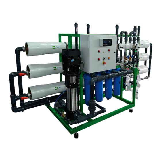
- Page 1 Ecosoft MO-12 Industrial Reverse Osmosis System Instruction manual...
-
Page 3: Table Of Contents
Acronyms and abbreviations RO system 1. Overview 2. Technical data 3. Installation and startup 4. Installation requirements 5. Operating requirements 6. Shipping and storage requirements 7. Troubleshooting CONTROLLER 1. Overview 2. Technical data 3. Operating modes 4. Program Annex. Operation record This appliance is not intended for use by persons (including children) with reduced physical, sensory or mental capabilities, or lack of experience and... -
Page 4: Acronyms And Abbreviations
Ecosoft industrial reverse osmosis systems are used for demi- neralizing water in industrial, municipal, commercial applications. Ecosoft RO system can be used to demineralize low to medium salinity feed water. All parts of the system that are in contact with water have the necessary certifications for use in food/drinking water applications. -
Page 5: Technical Data
Improperly commissioned RO system may fail in the matter of minutes, including irreparable membrane failure, hardware failure, and also involves electrical and pressure hazard. Drain flow rate and recycle flow rates should only be configured by authorized staff. Permeate stream comes out via permeate outlet and runs to permeate tank. - Page 6 SPECIFICATIONS Rated capacity ±10%, m Feed water flowrate @ 0,2-0,4 MPa, m 16-20 Water use per rinse, L Power consumption, kW Dimensions (W×D×H), m 4,2 × 1,4 × 2,1 Maximum dry weight, kg 1000 Connection port sizes feed water DN65 permeate DN50 concentrate...
-
Page 7: Installation And Startup
Installation and startup Caution! Electrical installation should only be done by a qualified electrician. 3.1 Rest the unit on a flat level surface capable of supporting its weight (see table of Specifications). Install permeate tank next to the unit. Inspect the RO system carefully for damage, including piping, valves and instruments, pump, pressure vessels, pre-filter housings, power cabinet before proceeding with connection and startup. - Page 8 If installing multiple membranes in one vessel, proceed with the next membrane in a similar fashion, after installing membrane connector in central tube of first membrane’s rear end. Couple the second membrane with the connector, then push it forward all the way in the pressure vessel. After the membrane(s) are installed in the pressure vessel, install the lid back in place.
- Page 9 together on controller PCB. Then, run wire from microswitch inside the controller housing and connect to the terminals. If using antiscalant or other RO chemicals, refer to dosing pump’s instruction booklet for information concerning the dosing pump. 3.6 Run power to the RO system. Pull power cable inside power cabinet of the RO system through a gland in cabinet wall.
- Page 10 3.7 Start up the system as fol lows: 3.7.1 Ensure recycle and drain flow regulating valves are fully open before starting. Run the permeate tube to drain for the duration of the first run of the RO system. 3.7.2 Switch on controller circuit breaker to start the RO system. After the controller starts up and the unit starts to operate, tighten drain regulating valve until drain rotameter reading meets specification (see table of Specifications).
-
Page 11: Installation Requirements
Take care not to exceed 1,6 MPa in membrane module at any time. If membrane pressure rises above the upper limit in specification, open recycle flow regulating valve to bring it down. Drain flow rate must not drop smaller than the calculated target value at any time. -
Page 12: Operating Requirements
• Electrical connections must comply with local electrical code. Make sure to follow applicable grounding and insulation rules. • Supply, drain, and delivery pipework must comply with local plumbing code and have sufficient flow capacity. Drain line of the unit must be separated from floor drain with an air gap. •... - Page 13 5.5 Change polypropylene cartridge when it has clogged. Pressure drop of 0,1 MPa or greater on the sediment filter indicates that filter cartridge needs to be replaced as soon as possible. 5.6 Perform CIP or another suitable chemical cleaning protocol when any of the following conditions are encountered: –...
- Page 14 remove spent cartridge from the bowl, place a clean one inside – and screw the bowl back on. Do not torque over 2 kgf×m when tightening bowl. 5.10 To replace membrane element proceed as follows: – remove the power from the unit; –...
-
Page 15: Shipping And Storage Requirements
Shipping and storage requirements • The unit must be stored indoors. Ambient air quality must meet workplace standards. • Carry out preservative treatment of membrane elements when preparing for an extended downtime. • The RO machine in its original packaging can be shipped by all types of air, sea or ground transport. -
Page 16: Troubleshooting
Power supply fault Refer to protection relay manual or contact Ecosoft product support The controller Protection relay is Ensure clean 380-400 V, 50 Hz does not start tripped... - Page 17 The system is Set up proper connection to connected to water water supply pipe. Avoid long supply using flexible runs of small size pipe hose or small size pipe Clogged pre-filter Check the filter cartridge and cartridge replace if necessary Other Contact your dealer’s product support...
-
Page 18: Controller
• performing hydraulic flushing of membranes (‘forward flush’) with preset frequency and duration; • implementing manual control over the unit. In order to deliver the above functionality, Ecosoft process controller supports the following connectivity: – 5 dry contact switches (NC/NO);... -
Page 19: Technical Data
Technical data Specifications Electrical rating 230 V, 50-60 Hz, 6 A fuse Power 4 VA IP code IP 65 Ambient temperature 5…40 °C Weight 0,25 kg Dimensions (L×W×H) 60×120×250 mm Permeate conductivity ranges 0…50 μS/cm 0…1000 μS/cm Screw terminal pinout DESCRIPTION DESIGNATOR PIN #... -
Page 21: Operating Modes
Operating modes When operating, the controller will be in any one of the following modes: Service, Stop, Forward Flush 1, Forward Flush 2, Standby, Fault. Immediately after starting, the controller will display firmware version and then proceed to Service if tank permeate level is low and backpressure switch is not activated. - Page 22 (OC5000 only). Pushing START once will initiate Forward Flush 1, pushing START twice in 0.5 seconds or less will initiate Forward Flush 2, pushing STOP will bring on Stop mode. If high feed pressure, low feed pressure, or high permeate conductivity condition occurs, the controller will go into Fault mode.
- Page 23 Forward Flush 2 occurs after each Forward Flush 1 if configuration step 1.3 is set to non-zero value. It can be manually brought on by pushing START during Forward Flush 1 or double pushing START during Service. Status of outputs in FF2 High pressure and on (if configuration step 1.4 is set to antiscalant pumps...
- Page 24 the controller back to Standby. When float switch or permeate backpressure switch deactivate, the controller will go back to Service. FAULT In Fault mode, the unit is stalled to protect the equipment from dangerous operating conditions. Fault mode is brought on by activating low feed pressure switch (to prevent ‘dry running’), high feed pressure switch (to protect against overpressure), or reading an excessively high permeate conductivity value (which could mean...
-
Page 25: Program
Program Configuration settings are stored in non-volatile memory. Access to each submenu is protected with passcode. To enter configuration menu, hold STOP for 8 seconds. In the menu, editing and storing values is helped by flashing cursor. START button moves cursor one position to the right, ... - Page 26 2. CALIBRATION Settings and calibration passcode prompt 2.1 First point value, μS/cm 2.2 Second point value, μS/cm 3. MAINTENANCE Maintenance passcode prompt 3.1 Schedule maintenance stop, on/off 3.2 Scheduled stop period, h (if 3.1 is set to ‘on’) 500 hour 3.3 New maintenance passcode 1.
- Page 27 1.7 Read low feed pressure during Forward Flush This setting specifies if low feed pressure switch status will be read by the controller during forward flush. If set to ‘off’, low feed pressure situation will not bring about Fault mode. 1.8 Low feed pressure switch This setting specifies whether low feed pressure switch is normally closed (NC) or normally open (NO) type.
- Page 28 reset to ‘off’ if 1.16 is set to ‘on’. 1.16 0…50 μS/cm conductivity range Specify if the controller will read electrical conductivity of permeate in the range of 0…50 μS/cm (on/off). This setting will reset to ‘off’ if 1.15 is set to ‘on’. 1.17 Permeate conductivity Fault threshold Specify maximum acceptable permeate conductivity.
- Page 29 into sample of known standard conductivity, wait until the reading on display stabilizes and input actual conductivity. Then go to the next step. 2.2 Second point value Use water sample with greater conductivity than that of the first point standard. Follow the same procedure rinsing and wiping residual moisture on conductivity meter electrodes.
-
Page 30: Annex. Operation Record
Operation log sample Ecosoft RO . Operation record. Pressure Flow Notes...
Need help?
Do you have a question about the MO-12 and is the answer not in the manual?
Questions and answers