
Related Manuals for WEISS ROBOTICS CRG Series


Summary of Contents for WEISS ROBOTICS CRG Series
- Page 1 Mounting and Operating Manual CRG Series - Electrical Gripping Modules with IO-Link October 2020...
-
Page 2: Table Of Contents
Contents Introduction ...................... 4 Product Specification ....................4 Applicable Documents ....................4 Target Audience ......................5 Notation and Symbols ....................5 Basic Safety Notes....................5 Intended Use ........................ 5 Environmental and Operating Conditions ..............6 Product Safety ......................6 2.3.1 Protective Equipment ...................... - Page 3 State visualization by luminous ring ................19 Non-volatile Memory ....................19 Interface Description IO-Link ................21 Cyclic Process Data ..................... 21 8.1.1 Output Data (IO-Link Master to Gripping Module) ............. 21 8.1.2 Input Data (Gripping Module to IO-Link Master) ..............22 Acyclic Process Parameters and System Commands .............
- Page 4 9.13.2 Application Example Internal Gripping ................51 9.14 Function Block for Siemens TIA Portal ................. 52 Maintenance and Cleaning ................53 10.1 Needs-based Maintenance ..................54 10.2 Resetting the Maintenance Interval Count ..............54 Troubleshooting ....................55 11.1 The Base Jaws Do Not Move ..................55 11.2 Gripping Module Stops Abruptly or Does Not Complete the Entire Stroke ....
-
Page 5: Introduction
This manual is an integral part of the gripping module and describes the safe and proper handling during all operational phases. It is valid solely for gripping modules of the CRG series and contains important infor- mation on assembly, commissioning, maintenance, and service. -
Page 6: Target Audience
Please find additional information about the warranty in our general terms and conditions, available online at https://www.weiss-robotics.com/en/general-terms-and-conditions. 1.3 Target Audience These instructions are targeted at plant manufacturers and operators, who should make this and other doc- uments permanently available for the personnel and should also ask the personnel to read and observe par- ticularly the safety instructions and warnings. -
Page 7: Environmental And Operating Conditions
2.3.2 Constructional Changes, Attachments, or Modifications Additional bore holes, threads, or attachments not offered by Weiss Robotics as accessories may be mounted only after obtaining the written approval of Weiss Robotics. 2.3.3 Special Standards The following standards are met: •... -
Page 8: Personnel Qualification
2.5 Safety Considerations Even though the CRG series are for the collaborative operation, the safety and accident prevention reg- ulations valid at the operation site must be observed. Do not move parts by hand when the module is connected to the power supply. -
Page 9: Scope Of Delivery And Accessories
4 Scope of Delivery and Accessories The scope of delivery comprises: • Gripping module CRG in the version ordered • Accessory kit (centering sleeves or dowel pins matching the module's diameter) • Quick guide CRG series Item CRG 30-050 CRG 200-085... -
Page 10: Technical Data
5 Technical Data 5.1 Nominal Mechanical Data Exceeding the specified nominal data may damage the module. If in doubt, please discuss your ap- plication with our technical sales department. Mechanical operating data Unit CRG 30-050 CRG 200-085 Total stroke Nominal gripping force (100%) Recommended minimum gripping force (50%) Max. -
Page 11: Gripping Force And Finger Speed
Figure 2: Determination of the finger length “L”. Left: straight fingers, right: angled fingers 5.1.2 Gripping Force and Finger Speed The gripping force can be set as a percentage of the nominal gripping force. The recommended minimum gripping force is 50% of the nominal gripping force. The gripping module sets the finger speed depending on the parameterized gripping force, see Figure 3. -
Page 12: Cycle Times
Gripping speeds exceeding 100% (override) lead to an increased gripping impulse that can damage the part that is being gripped and the gripping mechanism. 5.1.3 Cycle Times The following diagrams show the typical progression of gripping time and release time for different gripping force settings. -
Page 13: Max. Permitted Finger Load
5.1.4 Max. Permitted Finger Load The following table shows the maximum permitted static loads on the base jaw guide. Load Unit CRG 30-050 CRG 200-085 1890 26.0 23.6 Table 4: Static guide loads In the case of overlaid forces and torques, the carrying capacity of the guide must be recalculated according to the following equation: ����... -
Page 14: Nominal Electrical Data
5.2 Nominal Electrical Data Exceeding the specified nominal data may damage the module. If in doubt, please discuss your ap- plication with our technical sales department. Electrical operating data Unit CRG 30-050 CRG 200-085 Supply voltage 18 ... 30 Typ. current drawn (state IDLE) Max. -
Page 15: Name Plate
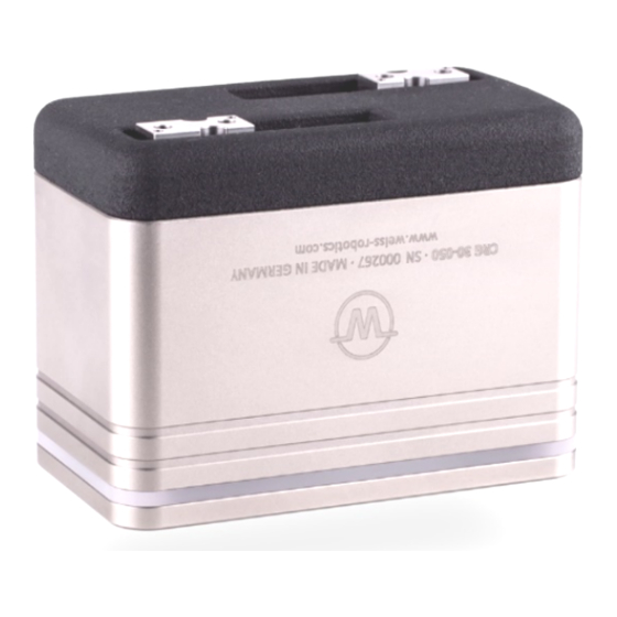
Signal Function Power supply +24 V L+ (1) Q (2) Reserved, do not connect! L- (3) C/Q (4) Power Supply 0 V IO-Link communication Figure 5: Pin assignment (view on connector) 5.3 Name Plate The name plate is on the transverse side of the gripping module and contains the serial number, the hardware version, and the exact type designation. -
Page 16: Installation And Commissioning
6 Installation and Commissioning Risk of injury due to unexpected movements of the machine. Disconnect the module from the power supply during all maintenance work/adjustments and make sure the module is force-free. 6.1 Installation You can find the dimensions of the threads and centering holes that can be used to mount the module in the technical drawing of the respective build size. - Page 17 CRG 200-085 2 pieces 2 pieces Centering sleeve 6h6 x 5,5 Centering sleeve 6h6 x 5,5 Weiss Robotics part no. 2090046 Weiss Robotics part no. 2090046 2 pieces 2 pieces Screw ISO 4762 - M4 Screw ISO 4762 - M4...
-
Page 18: Functional Principle Of The Gripping Module
Due to the pre-positioning capability of the gripping fingers and the innovative gripping force control, the gripping modules of the CRG series can be used for a multitude of applications in modern automation. The module is supplied with power and connected to the process control directly via the integrated IO-Link interface. -
Page 19: Typical Application
7.1 Typical Application Figure 9 shows a typical control-side setup with CRG series gripping modules that are accessed via PLC and a decentralized IO-Link field bus coupler. If you need assistance in selecting the IO-Link components, please contact our technical support. -
Page 20: State Visualization By Luminous Ring
gripping part and thus minimize the risk of falling down or ejecting workpiece. The Gripping force retention works regardless of the gripping direction and required no configuration. Damage to the gripping module possible: Do not move the gripping jaw by hand in the currentless state. - Page 21 • Protocol memory (event log) of the last ten events • Data for needs-based maintenance (gripping cycle count) The protocol memory can be read out via IO-Link (parameter index 0x100 to 0x109, cf. Table9). - 20 -...
-
Page 22: Interface Description Io-Link
8 Interface Description IO-Link The interface description of the IO-Link interface is defined in the IO-Link Device Description (IODD) file that belongs to the gripping module. The IODD file that is needed for the configuration of the gripping module can be found on our website at https://www.weiss-robotics.com/crg under “Downloads”. 8.1 Cyclic Process Data Please pay attention to the byte order. -
Page 23: Input Data (Gripping Module To Io-Link Master)
VIS – Visualization Index (Bit 15…13, UIntegerT) This index selects one of eight preprogrammed visualization patterns for the luminous ring. RES – Reserved data bits (bit 12…11) These data bits are reserved and are currently not evaluated by the gripping module. Their value should always be set to 0 by the master. - Page 24 BYTE 0 BYTE 1 BYTE 2 BYTE 3 MAINT TEMPWARN TEMPFAULT FAULT HOLDING CLOSED OPEN IDLE Table 9: Process data word gripping module to IO-Link master POS – Current position (bit 31…16, IntegerT) Returns the current position of the base jaws in 1/100 mm. SW0, SW1, SW2, SW3 - Virtual positions switches 0 to 3 (bit 15…12, BooleanT) If the respective bit is set, the base jaws are within the parameterized position range of the respective virtual position switch.
-
Page 25: Acyclic Process Parameters And System Commands
TEMPFAULT – Temperature fault (bit 5, BooleanT) When the temperature inside the gripping module exceeds 70° C, this bit is set. It is recommended to stop the gripping module and only start it again after it has significantly cooled down. If necessary, the heat dissipation of the gripping module should be checked. -
Page 26: Remanent Storage Of Acyclic Process Parameters
The acyclic process parameters can be set and read out during configuration with a suitable configuration software. This configuration software is available from the manufacturer of your IO-Link master or field bus coupler. Altering parameters and issuing system commands during operation is possible on many PLC sys- tems with the respective function blocks (e.g. -
Page 27: Device-Specific Acyclic Process Parameters
Index Function Access Data type Description 0x02 System Command Write only UIntegerT(8) Execution of system commands Standardized device protection func- 0x0C Device Access Locks Read/write RecordT tion 0x10 Vendor Name Read only StringT Manufacturer name 0x11 Vendor Text Read only StringT Manufacturer text 0x12... - Page 28 Address Index 0x0040, Subindex 0x01 Data Type UIntegerT(8) - Value range: 10 to 200 Factory Setting Example: Gripping with 100% of the calculated gripping speed: Set the value 100. Gripping with double the calculated gripping speed: Set the value 200. Override Release Speed in Percent Limits the finger speed during releasing of the grip.
-
Page 29: Grip Parameters
8.2.3.2 Grip Parameters Four grips can be pre-parameterized. The factory settings depend on the build module type and are shown in Table 11. All grips have the same scope of functions and have the following parameters: NO PART Limit Indicates the NO PART Limit for the respective grip. When performing a grip, the gripping module tries to position the base jaws on this target position. - Page 30 Factory Setting See Table 11 Example: The RELEASE Limit for external gripping of a part is at 10 mm: Set the value 1000. Gripping Force Determines the required gripping force as a percentage of the nominal gripping force. The gripping speed is also determined via the gripping force, see chapter 5.1.2.
-
Page 31: Virtual Position Switches
8.2.3.3 Virtual Position Switches The gripping module has four virtual position switches. All position switches have the same scope of functions and can be set up via following parameters: Switch Position Indicates the center position of the switching range in 1/100 mm. Address Position switch 0: Index 0x0090, subindex 0x01 Position switch 1: Index 0x0091, subindex 0x01... -
Page 32: Visualization With Luminous Ring
8.2.3.4 Visualization with luminous ring The gripping module has a luminous ring that can be used to visualize different states of the application. For that purpose, eight visualization patterns can be parameterized. You can choose the animation, the color and the speed. - Page 33 Example: The animation should be as a clockwise rotating light: set the value 5 Color Choose color for visualization. Following colors are available: Value Color Value Color WHITE ORANGE LIGHT GREEN GREEN AQUAMARIN BLUE AZURE BLUE YELLOW VIOLET CYAN PINK MAGENTA Table 13: Available color For animations 0(GRIPPING STATE) and 14(RAINBOW) the color setting is ignored.
- Page 34 Speed Specifies the animation speed. The following speed values are available: Value Speed Value Speed STOP MEDIUM SLOWEST FAST SLOWER FASTER SLOW FASTEST Table 14: Available animation speed For animations 0 (GRIPPING STATE), 1 (OFF) and 2 (ON), the set speed is ignored. The speed 0(STOP) causes a permanent light when animation 3,4 and 9-13 are blinking.
-
Page 35: Diagnosis Parameters
Warning 2 (ON) 7 (ORANGE) Error 2 (ON) 1 (RED) Idle 5 (ROATING LIGHT CCW) 0 (WHITE) 4 (MEDIUM) Busy 5 (ROATATING LIGHT CCW) 2 (GRÜN) 4 (MEDIUM) User interaktion 5 (ROTATING LIGHT CCW) 3 (BLAU) 4 (MEDIUM) Alarm 3 (FLASHING) 1 (RED) 7 (Fastest) Table 15: Factory setting for illuminated ring visualisiation pattern... - Page 36 Current Module Temperature Indicates the current temperature inside the gripping module in 1/10 °C. Address Index 0x00A0, subindex 0x03 Data Type IntegerT(16) Factory Setting (not available) Example: A read-out value of 451 means a temperature of 45.1 °C. Cycle Count Indicates the total count of gripping cycles performed.
-
Page 37: Protocol Memory
A read-out value of -50112 means that the maintenance interval has been exceeded by 50112 gripping cycles. 8.2.3.6 Protocol Memory The protocol memory comprises ten entries, which can be read out via the device-specific acyclic process parameters. All entries are identical and are structured as follows: Time Stamp System time when the event occurs, measured in seconds since the boot-up of the module. -
Page 38: Extended Configuration Parameters
8.2.3.7 Extended Configuration Parameters Maintenance Interval Sets the number of gripping cycles for the maintenance interval. This value is preconfigured by the manufacturer and doesn’t need to be changed for normal operation. For certain applications, however, it might be useful to adjust the maintenance interval according to the environmental conditions of the gripping process. -
Page 39: System Events (Io-Link Events)
chapter 8.3), this command must be executed after maintenance has been performed. The maintenance count is then reset, and with it the system event and the respective bit in the cyclic process data word. Save Configuration Remanently (Code 0xE0). With this command, you can save the current configuration of the gripping module remanently. In case of power loss, the parameterization is still available. - Page 40 Code Event Description The gripping module has reached or exceeded the cycle count upon 0x8C41 Maintenance Required which the next maintenance is required. Maintenance must be car- ried out. Table 16: System events (IO-Link events) - 39 -...
-
Page 41: Control Of The Gripping Module
IO-Link master and the gripping module. The gripping module is also parameterized via IO-Link. This can be performed with the configuration software of the IO-Link master or with the DC-IOLINK device configurator by Weiss Robotics, which is available sepa- rately. -
Page 42: Position Sensors
Figure 12: Example: position value CRG 30-050 9.3 Reference Run In addition to the relative position measurement system, the gripping module CRG series has an absolute measuring system which provide the position of the base jaws directly after activating. Therefor a reference movement is not required. -
Page 43: Gripping State
You can determine the center position and the width of the detection range for each position switch. The position switches do not save their status but provide a momentary signal. To detect an end position reliably, it must be ensured mechanically that the fingers block in the position that is to be detected, e.g. by a me- chanical end stop or by the gripped part. -
Page 44: Parameterizable Grips
is executed and the gripping state changes accordingly. Every command leads to a change of state so the completion of a command can be identified by waiting for a change of state. Thus, the gripping state provides a simple opportunity to monitor the gripping process in the controlling PLC or robot control. -
Page 45: Gripping Direction
Grip Outside Grip Inside RELEASE Limit NO PART Limit RELEASE Limit NO PART Limit RELEASED HOLDING NO PART RELEASED HOLDING NO PART Position Position Part to be gripped Part to be gripped Figure 14: Gripping area and gripping direction If the base jaws are blocked outside the position window, e. g. at the end stop of the movement, the gripped part is considered released or no part has been detected, depending on the direction of movement. -
Page 46: Grip Part
9.7 Grip Part The program sequence for gripping a part is Figure 15. The gripping module must be initialized and activated before it can perform a grip (see chapter 9.6.1). The gripping direction depends on the parameterization of the respective grip. The module detects the end of the gripping process or an error by continuously monitor- ing the gripping state. -
Page 47: Troubleshooting
Figure 17 shows the program sequence that is required to acknowledge an error. If the error cannot be acknowledged, try to restart the gripping module by temporarily disconnecting it from the power supply. If the error persists, please contact the technical support of Weiss Robotics. The gripping module may be de- fective. -
Page 48: Activating And Deactivating The Module (Setup Mode)
EN = 0, HOME = 0 CMD = 0 Force-free (motor currentless) IDLE = 1 ? EN = 1, HOME = 0 CMD = 0 Base Jaws moving RELEASED = 1 ? Error acknowledged Part released Figure 17: Program sequence acknowledging an error and releasing a part 9.10 Activating and Deactivating the Module (Setup Mode) Especially when setting up the gripping process, it may be advisable to deactivate the gripping module. -
Page 49: Gripping Force Retention
EN = 1, HOME = 0 EN = 0, HOME = 0 CMD = 0 CMD = 0 INDEX = [Grip Index] INDEX = 0 Base Jaws moving RELEASED = 1 ? IDLE = 1 ? Module active and Module inactive open Figure 18: Program sequence to activate (left) and deactivate (right) gripping module 9.11 Gripping force retention... -
Page 50: Design Of The Gripping Process
Gripping state Animation Color IDLE Running light CCW White RELEASE Outward/ Innward Blue NO PART Outward/ Innward Blue HOLDING Green ERROR Flashing Table 18: Visualization the gripping states 9.13 Design of the Gripping Process The design of the gripping process determines the reliability of the production process. The following points have been proved to be helpful: •... -
Page 51: Application Example External Gripping
21 N. For the CRG 30-050, this means the gripping force is set to 70%. The part is parameterized as GRIP 0 of the gripping module. For this purpose, the following parameters are set via the configuration software of the IO-Link master or via the Weiss Robotics DC-IOLINK device configurator, which is available separately:... -
Page 52: Application Example Internal Gripping
selected as the visualization index to visualize the gripping state via the illuminated ring on the gripping mod- ule: In the released state, the illuminated ring shows an animation outwards in blue, if the part has been gripped correctly, the light shows green. 9.13.2 Application Example Internal Gripping In a mounting process, a plain bearing bush is to be picked up and inserted with an CRG 30-050. -
Page 53: Function Block For Siemens Tia Portal
To grip the part, the control system performs the program sequence depicted in Figure 15. When the GRIP command is issued, the fingers move apart since the NO PART Limit is higher than the RELEASE Limit. To release the part, perform the program sequence depicted in Figure 16. Since GRIP 1 has been parameterized in this example, the grip index 1 must also be used for performing the program sequences mentioned above. -
Page 54: Maintenance And Cleaning
10 Maintenance and Cleaning Damage to the gripping module due to inadequate lubrication possible. Perform some idle strokes traversing the whole movement range every 1000 gripping cycles and at least once a day to ensure an even distribution of the lubricant in the guides. Clean the gripping module in regular intervals with a dry cloth to remove all dirt and possible splinters. -
Page 55: Needs-Based Maintenance
10.1 Needs-based Maintenance When the maintenance function is activated, the gripping module triggers a system event when the mainte- nance interval has been reached. In addition, the MAINT flag is set in the cyclic process data. The remaining cycles until the maintenance interval is reached can be queried via the acyclic process parameters (see chap- ter 8.2.3.45). -
Page 56: Troubleshooting
• Restart the gripping module. If the error occurs again, send the gripping module to Weiss Robotics with a repair order. • Send the gripping module to Weiss Robotics with a repair or- Failure of a component, e.g. through over- der. -
Page 57: The Gripping Module Reports An Error
This error occurs when the base jaws do not move despite a move- ment command. If this error occurs repeatedly, the drive is defec- Motion error tive. Send the gripping module to Weiss Robotics with a repair or- der. The temperature inside the gripping module exceeds 70 °C. It is strongly recommended to stop the gripping module and only start it again after it has significantly cooled down. -
Page 58: Appendix A - Device-Specific Process Parameters
12 APPENDIX A - Device-specific Process Parameters Table9 lists the device-specific process parameters of the gripping module. A detailed description can be found in chapter 8.2.3. Index Funktion Zugriff Subindex Datentyp Beschreibung Werkseinstellung Override gripping Read /write UIntegerT(8) speed in percent Motion Override gripping 0x40... - Page 59 Index Funktion Zugriff Subindex Datentyp Beschreibung Werkseinstellung NO PART Limit in IntegerT(16) 1/100 mm RELEASE Limit in 0x65 Grip 5 Read /write IntegerT(16) 1/100 mm Gripping force in per- UIntegerT(8) cent NO PART Limit in IntegerT(16) 1/100 mm RELEASE Limit in 0x66 Grip 6 Read /write...
- Page 60 Index Funktion Zugriff Subindex Datentyp Beschreibung Werkseinstellung UIntegerT(8) Animation Virtualiza- 0x86 Read /write UIntegerT(8) Color tion 7 UIntegerT(8) Speed Switch position in IntegerT(16) 1/100 mm Virtual posi- 0x90 Read /write tion switch 0 Switch position in UIntegerT(16) 1/100 mm Switch position in IntegerT(16) 1/100 mm Virtual posi-...
- Page 61 Index Funktion Zugriff Subindex Datentyp Beschreibung Werkseinstellung Number of gripping Mainte- cycles after which 0x0140 nance Inter- Read /write UIntegerT(32) 2.000.000 maintenance is sig- naled Table 19: Device-specific process parameters - 60 -...
-
Page 62: Appendix B - Configuration Example
13 APPENDIX B - Configuration Example Below the configuration of Integration Line gripping modules via IO-Link with a suitable IO-Link master at a PLC is described. Control Elements Used • SPS SIEMENS Simatic S7-1200 1212C DC/DC/Rly version 4, article number 6ES7 212-1HE40-0XB0 •... - Page 63 Figure 22: Configuration of the IO-Link master Figure 23: Starting the S7-PCT port configurator (device tool) - 62 -...
- Page 64 Figure 24: Configuration of the IO-Link port - 63 -...
-
Page 65: Configuration Of The Gripping Module
13.3 Configuration of the Gripping Module The gripping module can now be parameterized via the S7-PCT port configurator. By clicking on “Online” (IO- Link port selected in the selection tree on the left), the port configurator establishes a connection to the IO- Link master. -
Page 66: Parameterization Of The Gripping Module
13.4 Parameterization of the Gripping Module The “Parameter” tab (Figure 26) shows the gripping parameters of the grip as well as the settings of the four virtual position switches. These values can be adjusted to your individual application. The system commands can be issued via buttons, e.g. acknowledging that maintenance has been performed or remanently storing the configuration data in the gripping module. -
Page 67: Diagnosis
13.5 Diagnosis The “Diagnosis” tab (Figure 27) shows various diagnosis data as well as the event log memory of the gripping module. This information can be read only. The “Diagnosis” tab provides information on the current state of the gripping module. Logged events can also be displayed. Figure 27: Diagnostics data of the gripping module in S7-PCT - 66 -... -
Page 68: Ec Declaration Of Incorporation
14 EC Declaration of Incorporation According to EC Machinery Directive 2006/42/EG, appendix II B Manufacturer Weiss Robotics GmbH & Co. KG Karl-Heinrich-Käferle-Str. 8 D-71640 Ludwigsburg Distributor Weiss Robotics GmbH & Co. KG Karl-Heinrich-Käferle-Str. 8 D-71640 Ludwigsburg We hereby declare that the following product:... - Page 69 © Weiss Robotics GmbH & Co. KG. All rights reserved. The technical data mentioned in this document can be changed to improve our products without prior notice. Used trademarks are the property of their respective trademark owners. Our products are not intended for...