Table of Contents
Advertisement
Available languages
Available languages
Quick Links
ELETTROVALVOLA NORMALMENTE CHIUSA AUTOMATICA PER GAS
AUTOMATIC NORMALLY CLOSED SOLENOID VALVE FOR GAS
ÉLECTROVANNE AUTOMATIQUE NORMALEMENT FERMÉE POUR GAZ
ELECTROVÁLVULA AUTOMÁTICA NORMALMENTE CERRADA PARA GAS
EVP.../NC - EVPC.../NC
CE-51CM4100
MADE IN ITALY
Omologazione CE secondo EN 161, conforme Regolamento (UE) 2016/426
EC approval according to EN 161, compliant with Regulation (EU) 2016/426
Homologation CE conformément à la norme EN 161, au Règlement (UE) 2016/426
Homologación CE según EN 161, conforme con el Reglamento (UE) 2016/426
Advertisement
Table of Contents

Related Manuals for Madas EVP Series


Summary of Contents for Madas EVP Series
- Page 1 ELETTROVALVOLA NORMALMENTE CHIUSA AUTOMATICA PER GAS AUTOMATIC NORMALLY CLOSED SOLENOID VALVE FOR GAS ÉLECTROVANNE AUTOMATIQUE NORMALEMENT FERMÉE POUR GAZ ELECTROVÁLVULA AUTOMÁTICA NORMALMENTE CERRADA PARA GAS EVP.../NC - EVPC.../NC CE-51CM4100 MADE IN ITALY Omologazione CE secondo EN 161, conforme Regolamento (UE) 2016/426 EC approval according to EN 161, compliant with Regulation (EU) 2016/426 Homologation CE conformément à...
- Page 2 INDICE - INDEX - INDEX - ÍNDICE pag. Italiano ................................ 3 English ................................ 15 Français ..............................27 Español ............................... 39 Disegni - Drawings - Dessins - Diseños ......................51 Dimensioni (tabella 1) ........................... 54 Dimensions (table 1) ............................. Dimensions (tableau 1) ..........................Dimensiones (tabla 1) ..........................
-
Page 3: Legenda Simboli
1.0 - GENERALITÀ Il presente manuale illustra come installare, far funzionare e utilizzare il dispositivo in modo sicuro. Le istruzioni per l’uso devono essere SEMPRE disponibili nell’impianto dove è installato il dispositivo. ATTENZIONE: le operazioni di installazione/cablaggio/manutenzione devono essere eseguite da personale qualificato (come indicato in 1.3) utilizzando adeguati dispositivi di protezione individuale (DPI). -
Page 4: Personale Qualificato
1.3 - PERSONALE QUALIFICATO Trattasi di persone che: • Hanno dimestichezza con l’installazione, il montaggio, la messa in servizio e la manutenzione del prodotto; • Sono a conoscenza delle normative in vigore nella regione o paese in materia di installazione e sicurezza; •... -
Page 5: Dati Tecnici
2.0 - DATI TECNICI • Impiego : gas non aggressivi delle tre famiglie (gas secchi) • Temperatura ambiente (TS) : -20 ÷ +60 °C • Tensioni di alimentazione (vedere tabella 2) : 12 Vdc - 12 V/50 Hz - 24 Vdc - 24 V/50 Hz - 110 V/50-60 Hz - 230 V/50-60 Hz* •... -
Page 6: Messa In Funzione Del Dispositivo
2.1 - INDIVIDUAZIONE MODELLI EVP/NC - EVPC/NC : Apertura rapida EVPF/NC - EVPCF/NC : Apertura rapida + regolazione portata 2.2 - LIVELLO SIL Il livello di SIL della elettrovalvola stand-alone è SIL 2; quando vengono installate due elettrovalvole in serie e il relativo controllo tenuta (Valve Proving System), certificato secondo EN 1643, il livello raggiunto è... - Page 7 Procedure in comune (apparecchi filettati e flangiati): • Deve essere prevista, in accordo alla normativa EN 161, l’installazione di un filtro adeguato a monte di un dispositivo di sicurezza di chiusura del gas; • In caso di installazione all’esterno, è consigliato prevedere una tettoia di protezione per evitare che l’acqua piovana possa danneggiare le parti elettriche dell’apparecchio.
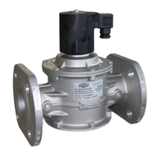
- Page 8 • La freccia, indicata sul corpo (4) dell’apparecchio, deve essere rivolta verso l’utenza; • Inserire all’interno dei bulloni le apposite rondelle per evitare danneggiamenti alle flange in fase di serraggio; • Durante la fase di serraggio prestare attenzione a non “pizzicare” o danneggiare la guarnizione; •...
- Page 9 • In ogni caso dopo l’installazione verificare la tenuta dell’impianto; • Non è consentito il cablaggio con cavi collegati direttamente alla bobina. Usare SEMPRE e SOLO il connettore indicato dal fabbricante; • Prima di cablare il connettore (1), svitare completamente e rimuovere la vite centrale (14). Usare gli appositi terminali per cavi (vedere figure sotto).
- Page 10 3.4 - ESEMPIO GENERICO DI INSTALLAZIONE (Rampa Bruciatore) 1. Filtro gas FM 7. Elettrovalvola automatica EVPCS/NC ad apertura lenta 2. Valvola di blocco OPSO serie MVB/1 MAX 8. Reset esterno 3. Regolatore di pressione RG/2MC 9. Burner control 4. Pressostato di minima pressione 10.
-
Page 11: Prima Messa In Servizio
4.0 - PRIMA MESSA IN SERVIZIO • Prima della messa in servizio verificare che tutte le indicazioni presenti in targhetta, inclusa la direzione del flusso, siano rispettate; • Dopo aver pressurizzato in maniera graduale l’impianto, verificare la tenuta e il funzionamento dell’elettrovalvola, alimentando/disalimentando elettricamente il connettore SOLO SE connesso alla bobina. - Page 12 5.1 - SOSTITUZIONE DEL CONNETTORE • Svitare completamente e rimuovere la vite centrale (14), successivamente sganciare il connettore (1) dalla bobina (11); • Dopo aver rimosso il cablaggio elettrico interno esistente, cablare il nuovo connettore e fissarlo alla bobina come indicato in 3.2; 5.2 - SOSTITUZIONE DELLA BOBINA •...
-
Page 13: Trasporto, Stoccaggio E Smaltimento
7.0 - TRASPORTO, STOCCAGGIO E SMALTIMENTO 6.2 - INSTALLAZIONE e TARATURA CPI SWITCH • Durante il trasporto il materiale deve essere trattato con cura, E’ necessario chiudere il gas prima dell’installazione. evitando che il dispositivo possa subire urti, colpi o vibrazioni; NOTA: Le operazioni di cablaggio del connettore CPI (20) devono •... -
Page 14: Dati Di Targa
9.0 - DATI DI TARGA In targa (vedere esempio a fianco) sono riportati i seguenti dati: • Nome/logo e indirizzo del fabbricante (eventuale nome/logo distributore) • Mod.: = nome/modello dell’apparecchio seguito dal diametro di connessione • CE-51CM4100 = numero pin di certificazione •... -
Page 15: General Information
1.0 - GENERAL INFORMATION This manual shows you how to safely install, operate and use the device. The instructions for use ALWAYS need to be available in the facility where the device is installed. ATTENTION: installation/wiring/maintenance need to be carried out by qualified staff (as explained in section 1.3) using appropriate personal protective equipment (PPE). -
Page 16: Qualified Staff
1.3 - QUALIFIED STAFF These are people who: • Are familiar with product installation, assembly, start-up and maintenance; • Know the regulations in force in the region or country pertaining to installation and safety; • Are trained in first aid. 1.4 - USING NON-ORIGINAL SPARE PARTS •... -
Page 17: Technical Data
2.0 - TECHNICAL DATA • Use : non-aggressive gases of the three families (dry gases) • Ambient temperature (TS) : -20 ÷ +60 °C • Supply voltages (see table 2) : 12 Vdc - 12 V/50 Hz - 24 Vdc - 24 V/50 Hz - 110 V/50-60 Hz - 230 V/50-60 Hz* •... -
Page 18: Commissioning The Device
2.1 - MODEL IDENTIFICATION EVP/NC - EVPC/NC : Fast opening EVPF/NC - EVPCF/NC : Fast opening + flow adjustment 2.2 - SIL LEVEL The SIL level of the stand-alone solenoid valve is SIL 2; when two solenoids are installed in series and the relative leak test (Valve Proving System), certified according to EN 1643, the achieved level is SIL 3, as set forth in EN 676:2008. - Page 19 Common procedures (threaded and flanged devices): • In accordance with EN 161 a suitable filter must be installed upstream of a gas closing safety device; • With outdoor installation, it is advisable to provide a protective roof to prevent rain from damaging the electrical parts of the device;...
- Page 20 • The arrow, shown on the body (4) of the device, needs to be pointing towards the application; • Insert the relative washers inside the bolts in order to prevent damage to the flanges during tightening; • When tightening, be careful not to “pinch” or damage the gasket; •...
- Page 21 • In any case, following installation, check the tightness of the plant; • Wiring cannot have cables connected directly to the coil. ALWAYS and ONLY use the connector identified by the manufacturer; • Before wiring the connector (1), unscrew and remove the central screw (14). Use proper cable terminals (see the figure below).
- Page 22 3.4 - GENERIC EXAMPLE OF AN INSTALLATION (Burner Gas Train) 1. FM gas filter 7. EVPS/NC slow opening automatic solenoid valve 2. OPSO series MVB/1 MAX shut off valve 8. External reset 3. RG/2MC pressure regulator 9. Burner control 4. Minimum pressure switch 10.
-
Page 23: First Start-Up
4.0 - FIRST START-UP • Before start-up make sure that all of the instructions on the rating plate, including the direction of flow, are observed; • After having gradually pressurised the system, check tightness and operation of the solenoid valve, electrically powering / disconnecting the connector ONLY IF connected to the coil. -
Page 24: Replacing The Coil
5.1 - REPLACING THE CONNECTOR • Unscrew and remove the central screw (14), then remove the connector (1) from the coil (11); • When you have taken out the existing internal electrical wiring, wire the new connector and secure it to the coil, as shown in 3.2; 5.2 - REPLACING THE COIL •... -
Page 25: Transport, Storage And Disposal
7.0 - TRANSPORT, STORAGE AND DISPOSAL 6.2 - CPI SWITCH INSTALLATION and CALIBRATION It is necessary to close the gas prior to installation. • During transport the material needs to be handled with care, NOTE: CPI connector (20) wiring must be do ensuring a avoiding any impact or vibrations to the device;... -
Page 26: Rating Plate Data
9.0 - RATING PLATE DATA The rating plate data (see example provided here) includes the following: • Manufacturer’s name/logo and address (possible distributor name/logo) • Mod.: = device name/model followed by the connection diameter • CE-51CM4100 = certification pin number •... -
Page 27: Légende Des Symboles
1.0 - GÉNÉRALITÉS Le présent manuel illustre comment installer et faire fonctionner le dispositif en toute sécurité. Les instructions pour l'utilisation doivent TOUJOURS être disponibles dans le site de production où le dispositif est installé. ATTENTION : les opérations d’installation/de câblage/d’entretien doivent être effectuées par un personnel qualifié... -
Page 28: Personnel Qualifié
1.3 - PERSONNEL QUALIFIÉ Il s'agit de personnes qui : • Sont familiarisées avec l'installation, le montage, la mise en service et l'entretien du produit; • Connaissent les réglementations en matière d'installation et de sécurité, applicables dans leur région ou leur pays; •... -
Page 29: Données Techniques
2.0 - DONNÉES TECHNIQUES • Emploi : gaz non agressifs des trois familles (gaz secs) • Température ambiante (TS) : -20 ÷ +60 °C • Tensions d'alimentation (voir le tableau 2) : 12 Vcc - 12 V/50 Hz - 24 Vcc - 24 V/50 Hz - 110 V/50-60 Hz - 230 V/50-60 Hz* •... - Page 30 2.1 - IDENTIFICATION DES MODÈLES EVP/NC - EVPC/NC : Ouverture rapide EVPF/NC - EVPCF/NC : Ouverture rapide + réglage du débit 2.2 - NIVEAU SIL Le niveau de SIL de l'électrovanne seule est SIL 2; si les deux électrovannes sont installées en série et le système de contrôle de l’étanchéité...
- Page 31 Procédures en commun (appareils filetés et bridés) : • Il faut prévoir, conformément à la norme EN 161, l'installation d’un filtre adapté en amont d'un dispositif de sécurité de fermeture du gaz ; • En cas d’installation à l’extérieur, il est conseillé de prévoir une protection aux intempéries pour éviter que les précipitations puissent endommager les parties électriques de l’appareil ;...
- Page 32 • La flèche, indiquée sur le corps (4) de l'appareil, doit être tournée vers l’application ; • Insérez les rondelles appropriées à l'intérieur des boulons pour éviter d'endommager les brides pendant le serrage ; • Pendant la phase de serrage, veillez à ne pas « pincer » ou endommager le joint ; •...
- Page 33 • Dans tous les cas, après la mise en place vérifier l’étanchéité de l’installation ; • Il n'est pas permis de câbler avec des câbles reliés directement à la bobine. Utiliser TOUJOURS et SEULEMENT le connecteur indiqué par le fabricant ; •...
- Page 34 3.4 - EXEMPLE GÉNÉRIQUE D’INSTALLATION (Rampe Brûleur) 1. Filtre à gaz FM 7. Électrovanne automatique EVPCS/NC à ouverture lente 2. Vanne de fermeture OPSO série MVB/1 MAX 8. Reset externe 3. Régulateur de pression RG/2MC 9. Burner control 4. Pressostat de pression minimum 10.
-
Page 35: Première Mise En Service
4.0 - PREMIÈRE MISE EN SERVICE • Avant la mise en service, s’assurer que toutes les indications présentes sur la plaque, y compris la direction du flux, sont respectées ; • Après avoir pressurisé progressivement l’installation, vérifier le joint d’étanchéité et le fonctionnement de l'électrovanne, en mettant sous tension/hors tension le connecteur UNIQUEMENT S’IL EST connecté... - Page 36 5.1 - REMPLACEMENT DU CONNECTEUR • Dévisser complètement et ôter la vis centrale (14), puis décrocher le connecteur (1) de la bobine (11); • Après avoir ôté le câblage électrique interne existant, câbler le nouveau connecteur et le fixer à la bobine comme indiqué au 3.2; 5.2 - REMPLACEMENT DE LA BOBINE •...
-
Page 37: Garantie
7.0 - TRANSPORT, STOCKAGE ET ÉLIMINATION 6.2 - INSTALLATION et RÉGLAGE CPI SWITCH • Pendant le transport, le matériel doit être traité avec soin, en évitant que Il est nécessaire de fermer le gaz avant l’installation. le dispositif ne puisse subir des chocs, des coups ou des vibrations ; REMARQUE : Les opérations de câblage du connecteur CPI •... - Page 38 9.0 - DONNÉES DE LA PLAQUE Dans les données de la plaque (voir l’exemple ci-contre) sont reportées les données suivantes : • Nom/logo et adresse du fabricant (éventuellement nom/logo du revendeur) • Mod. : = nom/modèle de l'appareil suivi par le diamètre de connexion •...
-
Page 39: Información General
1.0 - INFORMACIÓN GENERAL Este manual ilustra cómo instalar y hacer funcionar el dispositivo de forma segura. Las instrucciones de uso deben estar SIEMPRE disponibles en la instalación donde se encuentra el dispositivo. ATENCIÓN: las operaciones de instalación/cableado/mantenimiento las debe realizar personal cualificado (como se indica en 1.3), utilizando equipos de protección individual (EPI) adecuados. -
Page 40: Personal Cualificado
1.3 - PERSONAL CUALIFICADO Se trata de personal que: • Está familiarizado con la instalación, el montaje, la puesta en servicio y el mantenimiento del producto; • Conoce las normativas en vigor en la región o país en materia de instalación y seguridad; •... -
Page 41: Datos Técnicos
2.0 - DATOS TÉCNICOS • Uso : gases no agresivos de las tres familias (gases secos) • Temperatura ambiente (TS) : -20 ÷ +60 °C • Tensiones de alimentación (véase la tabla 2) : 12 Vcc - 12 V/50 Hz - 24 Vcc - 24 V/50 Hz - 110 V/50-60 Hz - 230 V/50-60 Hz* •... - Page 42 2.1 - IDENTIFICACIÓN DE MODELOS EVP/NC - EVPC/NC : Apertura rápida EVPF/NC - EVPCF/NC : Apertura rápida + regulación de caudal 2.2 - NIVEL DE SIL El nivel de SIL de la electroválvula aislada es SIL 2; cuando se instalan dos electroválvulas en serie junto con el respectivo control de estanqueidad (Valve Proving System), certificado según EN 1643, el nivel alcanzado es SIL 3, como se indica en la norma EN 676:2008.
- Page 43 Procedimientos en común (aparatos roscados y embridados): • De acuerdo con la normativa EN 161, la instalación debe equiparse con un filtro adecuado aguas arriba de un dispositivo de seguridad de cierre del gas; • En caso de instalación al exterior, se recomienda colocar un techo de protección para evitar que el agua de lluvia pueda dañar las partes eléctricas del aparato;...
- Page 44 • La flecha, indicada en el cuerpo (4) del aparato, debe estar dirigida hacia el punto de consumo; • Introduzca dentro de los pernos las arandelas correspondientes para evitar daños a las bridas en fase de apriete; • Durante la fase de apriete, asegúrese de no “pellizcar” ni dañar la junta; •...
- Page 45 • En cualquier caso, después del montaje compruebe la estanqueidad de la instalación; • No se permite el cableado con cables conectados directamente a la bobina. Use SIEMPRE y SOLAMENTE el conector indicado por el fabricante; • Antes de cablear el conector (1), desatornille completamente y quite el tornillo central (14). Utilice los oportunos terminales para cables (consulte las siguientes figuras).
- Page 46 3.4 - EJEMPLO GENÉRICO DE INSTALACIÓN (Rampa de quemador) 1. Filtro de gas FM 7. Electroválvula automática EVPCS/NC de apertura lenta 2. Válvula de seguridad por máxima OPSO serie MVB/1 MAX 8. Reset externo 3. Regulador de presión RG/2MC 9. Control del quemador 4.
-
Page 47: Primera Puesta En Servicio
4.0 - PRIMERA PUESTA EN SERVICIO • Antes de la puesta en servicio, compruebe que se respeten todas las indicaciones presentes en la placa, incluida la dirección del flujo; • Después de presurizar de forma gradual la instalación, compruebe la estanqueidad y el funcionamiento de la electroválvula, suministrando y quitando la alimentación eléctrica al conector SOLO SI está... - Page 48 5.1 - SUSTITUCIÓN DEL CONECTOR • Desenrosque completamente y quite el tornillo central (14), a continuación, desinstale el conector (1) de la bobina (11); • Después de haber quitado el cableado eléctrico interior existente, cablee el nuevo conector y fíjelo a la bobina, tal como se indica en el punto 3.2.
- Page 49 7.0 - TRANSPORTE, ALMACENAMIENTO Y ELIMINACIÓN 6.2 - INSTALACIÓN Y CALIBRACIÓN DEL MICROINTERRUPTOR CPI • Durante el transporte, el material debe tratarse con cuidado, evitando Hay que cerrar el gas aguas arriba de la instalación. que el dispositivo se someta a choques, golpes o vibraciones; NOTA: Las operaciones de cableado del conector CPI (20) se •...
- Page 50 9.0 - DATOS DE LA PLACA En la información de la placa (véase el ejemplo de al lado) aparecen los siguientes datos: • Nombre/logotipo y dirección del fabricante (eventual nombre/logotipo del distribuidor) • Mod.: = nombre/modelo del aparato seguido del diámetro de conexión •...
- Page 51 fig. 1 fig. 2 - EVP/NC DN 25 - P. max 360 mbar EVP/NC DN 15 - DN 20 - P.max 200- 360 mbar EVPC/NC DN 25 - P.max 200- 360 mbar 2,5mm...
- Page 52 fig. 4 fig. 3 EVPC/NC DN 50 P.max 200 mbar EVPC/NC DN 32 - DN 40 P.max 200 mbar EVPC/NC DN 32 - DN 40 - DN 50 P.max 360 mbar Modelli con predisposizione per CPI switch Models with set-up for CPI switch Modèles avec prédisposition pour CPI switch Modelos con predisposición para microinterruptor CPI...
- Page 53 fig. 1, 2, 3, e 4 fig. 1, 2, 3 and 4 fig. 1, 2, 3 et 4 fig. 1, 2, 3 y 4 1. Connettore elettrico 1. Electric connector 1. Connecteur électrique 1. Conector eléctrico 2. O-Ring di tenuta coperchio 2.
- Page 54 Tabella 1 - Table 1 - Tableau 1 - Tabla 1 Dimensioni di ingombro in mm - Overall dimensions in mm - Dimensions d’encombrement en mm - Dimensiones totales en mm Attacchi filettati B=(D+E) Threaded connections P. max EVP... EVPF... EVP...
- Page 55 Tabella 2a - Table 2a - Tableau 2a - Tabla 2a Bobine e connettori - Coils and connectors - Bobines et connecteurs - Bobinas y conectores Modello/Ø Voltaggio Codice bobina Timbratura bobina Codice connettore Potenza assorbita Cicli/ora Model/Ø Voltage Coil code Coil stamping Connector code Energy...
- Page 56 Tabella 2b - Table 2b - Tableau 2b - Tabla 2b Bobine e connettori - Coils and connectors - Bobines et connecteurs - Bobinas y conectores Modello/Ø Voltaggio Codice bobina Timbratura bobina Codice connettore Cicli/ora* Potenza assorbita Absorbed power Model/Ø Voltage Coil code Coil stamping...
- Page 57 Tabella 2c - Table 2c - Tableau 2c - Tabla 2c Bobine e connettori - Coils and connectors - Bobines et connecteurs - Bobinas y conectores Modello/Ø Codice bobina Timbratura bobina Codice connettore Cicli/ora* Potenza assorbita Voltaggio Absorbed power Model/Ø Coil code Coil stamping Connector code...
- Page 58 Tabella 3 - Table 3 - Tableau 3 - Tabla 3 SIL LEVEL Parameter Value Hardware Failure Tolerance - HFT Common Cause Failure - CCF in points Safe Failure Fraction - SFF in % Expected Lifetime Cycles - B 251278 Expected Lifetime - T [years] Probability of Dangerous Failures - PFH...
- Page 59 Diagramma perdite di carico (calcolato con P1 = 50 mbar) Pressure drop diagram (calculated with P1 = 50 mbar) Diagramme de perte de charge (calculé avec P1 = 50 mbar) Diagrama de pérdidas de carga (calculado con P1 = 50 mbar) dv = densità...
- Page 60 Nos reservamos el derecho de realizar cualquier cambio técnico y estructural. Sede legale: Via V. Moratello, 5/6/7 - 37045 Z.A.I. Legnago (VR) Italy Unità locale: Via M. Hack, 1/3/5 - 37045 Z.A.I. Legnago (VR) Italy Tel. +39 0442/23289 - Fax +39 0442/27821 - http://www.madas.it - e-mail: info@madas.it...
Need help?
Do you have a question about the EVP Series and is the answer not in the manual?
Questions and answers