Table of Contents

Related Manuals for Axi STS 6003


Summary of Contents for Axi STS 6003
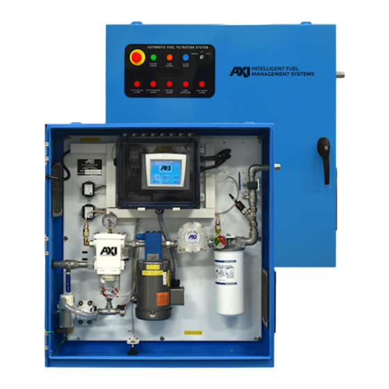
- Page 1 STS 6003 | 7003 Instruction, Operating, & Maintenance Manual ENCLOSED FUEL MAINTENANCE SYSTEM REV03016703010220 5400 Division Dr. | Fort Myers, FL 33905 239 690-9589 | Toll Free 877-425-4239 | FAX 239 690-1195 www.AXI-International.com...
- Page 2 REV03016703010220...
-
Page 3: Table Of Contents
Table of Contents Table of Contents ................................2 General Overview ................................4 STS 6003 | 7003 Specifications ............................4 System Components ................................5 Control and Safety Devices ..............................5 Pump/Motor ..................................5 Primary Filter/Water Separator ............................5 Fuel Conditioner ................................. 5 Fine Filter ................................... - Page 4 Troubleshooting ................................22 Symptom Troubleshooting Guide ............................. 22 AXI International Limited Warranty ..........................23 Warranty Claim Procedure ............................... 24 Technical Assistance and Ordering ..........................25 Accessories and Additional Configuration Parameters ....................25 Replacement Filter Elements ............................25 System Identification ................................ 25...
-
Page 5: General Overview
General Overview STS 6003 | 7003 Specifications Nominal Flow Rate…………………………………………….. 3 GPM/180 GPH (11.4 LPM/681.4 LPH) 1,440 gallons (5,451 liters) per 8-hour shift 4,320 gallons (16,353 liters) per 24-hour shift Primary Filter…………………………………………………… 10 or 30μ Particulate or 60μ Stainless Steel Screen with Centrifugal Water Separator Secondary Filter……………………………………………….. -
Page 6: System Components
System Components Control and Safety Devices • System Controller Incorporated PLC-based Timer Memory retention during power outages Alarm Indicator Light(s) Control Circuit Breakers (CB1, CB2) Pump Control Selector Switch {Hand (Manual) / Off / Auto} Alarm Reset Push Button Pump Running Indicator Light System Power Indicator Light Emergency Stop (E-Stop) Push Button 6000 Series Controller:... -
Page 7: Auto Water Drain (Awd) Assembly - If Applicable
If Applicable Auto Water Drain (AWD) Assembly – • Accessory Pump • Additional Water Detection Alarm Module • Additional Pair of Water Detection Sensor Probes • Solenoid Drain Valve • Basket Strainer • Water Collection Drum High Water Level Float Switch If Applicable Manual Additive Injection –... -
Page 8: System Operation
Note: If the Pump Overload Alarm triggers, please contact AXI International. Once triggered alarms are addressed, each alarm can be reset via the Alarm Reset button on the enclosure door panel. -
Page 9: Multi-Tank - If Applicable
Note: For information on factory set points or timer delays please refer to the “Accessories and Additional Configuration Parameters” subsection in the “Technical Assistance and Ordering” section. If Applicable Multi-Tank – 1. From the Main Menu screen select “CONFIG” 2. Enter password (9999) 3. -
Page 10: Auto Additive Injection - If Applicable
7. After injecting the desired amount of additive, close the Injection Port Ball Valve and return the System Ball Valve to the fully open position If Applicable Auto Additive Injection – 1. To start Auto Additive Injection, navigate from the Main Menu to the Additive Injection screen on the HMI. 2. -
Page 11: Primary Inspection
Primary Inspection Upon arrival, the system and accessories must be visually inspected before installation. Improper handling during shipping may cause physical or electrical problems. Immediately report or note any damages to the shipper. Checklist If the packing crate shows signs of damage inspect the system for damage. Check the entire system for damage that could indicate internal mechanical or electrical problems. -
Page 12: Installation
If the motor is running in the wrong direction, contact AXI International immediately. !WARNING!: The whole system (enclosure, plumbing, motor, electric sub panel) must be properly grounded for operator safety. -
Page 13: Typical Plumbing Installation (Schematically)
Use proper quality approved fuel line materials with similar inner diameter (ID) to the inlet/outlet of the system. For extended suction side plumbing runs, it is recommended to install oversized pipe, (1/4” to 1/2” increased ID) (Ref.: Page 4 – Suction Capability). Note: Flexible plumbing is strongly recommended for system inlet and outlet connections to external plumbing in order to avoid issues with thermal expansion, prevent putting any stress on the internal fittings of the system, and enable ease of maintenance/installation. - Page 14 The provided external High Tank Fuel Level Alarm Inputs (see provided electrical drawings) must be wired to the Normally Closed High Level Alarm Contacts on both tanks to avoid overfilling of either tank and potential spills. This is a very important safety feature that will shut the STS pump down in case a tank reaches an unsafe high level of fuel.
-
Page 15: Controller
Setting the Current Date and Time (7000 Series Controller) 1. Please make sure the pump is set to “OFF”. 2. On the home screen, long-press (for a few seconds) to the right of the AXI logo until a new screen appears. 3. Select ‘Enter Info Mode’. -
Page 16: Touchscreen Menu Structure (7000 Series Controller)
3. To set up a runtime simply enter a ‘Start’ and ‘Stop Time’ (using military format) in one of three timer boxes for the desired weekday. 4. To toggle between weekdays, simply press the available buttons on the left or right of the screen labeled with the abbreviation for the previous or next day in the week (e.g. -
Page 17: Priming The System
Priming the System The pump supplied with the system is NOT automatically self-priming and must not be run dry. !WARNING! If the pump is allowed to run without fuel, pump damage can occur. Priming Procedure The head of the pump on the system is shipped from the factory filled with No. 2 Diesel Fuel Oil in it to facilitate initial lubrication. -
Page 18: Commissioning/Initial Start-Up
Switch Adjustments Note: Please contact AXI International before adjusting either the vacuum or the pressure switch to avoid voiding the system’s warranty. Vacuum and Pressure Switches When the value exceeds the set point of the switches’... -
Page 19: Initial Test Procedures
The pump should immediately turn off and the “Tank Overflow” alarm should be indicated on the System Controller. Reset the alarm by pushing the Alarm Reset button on the enclosure door panel. Note: If any of the above described alarm test procedures fail or if any alarm trip value deviates, immediately contact AXI International. -
Page 20: Maintenance
Maintenance The system should be visually inspected and tested a minimum of every six (6) months according to the procedure below during light duty cycles. Monthly inspections are recommended for systems that are being used in excess of an average of eight (8) hours a day and five (5) days a week. Preventative Maintenance Prior to performing the maintenance procedure ensure that: 1. -
Page 21: Servicing The Fine Filter
13. Open the inlet and outlet ball valves on the system. 14. Press the Alarm Reset button on the enclosure door panel to acknowledge the alarm and reset it, if needed. 15. Return the selector switch to its original position and check for leaks when re-starting and pressurizing the system. - Page 22 Servicing Water Collection Drum: 1. Keep a fuel waste container below the Manual Drain Port (Please see Step 3). 2. Remove the Float Switch from the Water Collection Drum. 3. Properly dispose contents of the Water Collection Drum in accordance with the proper AHJ. 4.
-
Page 23: Troubleshooting
Troubleshooting Symptom Troubleshooting Guide No fuel delivery Pump requires too much power 1. Pump does not run 1. Liquid too viscous 2. Pump is not primed 2. Bent pump shaft, binding rotor 3. Fuel supply line blocked 3. Misalignment of pump/motor coupler 4. -
Page 24: Axi International Limited Warranty
This warranty is not intended to supplant normal inspection, care and service of the products covered by the user, and shall not obligate AXI International to provide free service during the warranty period to correct breakage, maladjustment, or other difficulties arising out of abuse, misuse, or improper care and maintenance of such products. Our... -
Page 25: Warranty Claim Procedure
AXI International reserves the right at any time to make changes in the design, material, function and specifications of its products. Any such changes shall not obligate AXI International to make similar changes in such products that were previously manufactured. -
Page 26: Technical Assistance And Ordering
Fort Myers, FL 33905 Tel: +1-239-690-9589 Fax: +1-239-690-1195 Email: info@axi-international.com Internet: www.axi-international.com Please provide the following information: Serial Number of your system, the required part numbers and quantity. The drawings/parts list included in this manual are the most accurate source of part numbers.
Need help?
Do you have a question about the STS 6003 and is the answer not in the manual?
Questions and answers