Table of Contents

Related Manuals for Axi MTC-X


Summary of Contents for Axi MTC-X
- Page 1 MTC-X INSTRUCTION, OPERATING AND MAINTENANCE MANUAL Tank Cleaning and Fuel Restoration System 1.239.690.9589 1.877.425.4239 Toll Free AXI.International AXInternational AXIFuel AXIFuel www.AXI-International.com REV0303MTCX010318...
- Page 2 MTC-X Mobile Fuel Polishing System The MTC-X Mobile Fuel Polishing System is designed to efficiently and safely clean and restore fuel to pristine condition. The MTC-X incorporates a multi-stage filtration process that reconditions, stabilizes, and decontaminates diesel, biofuels, light oils, and hydraulic fluids.
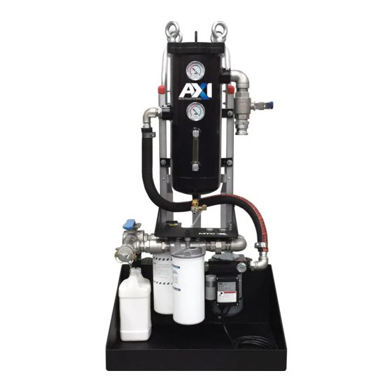
- Page 3 Discharge Port (Cam and Groove) Diverter Ball Valve No-Spill Accessory Switch Water Level Indicator Pump Vacuum Gauge Static Head Vacuum Gauge MTC SYSTEM INTEGRATION: MTC-X OPTIONS: AFC 705/710 Fuel Catalyst Spill Containment Berm Digital Flow Meter REPLACEMENT FILTER OPTIONS: Fine Filter Part No.
-
Page 4: Table Of Contents
Table of Contents General Overview ................................Primary Inspection ................................Checklist ..................................System Components ................................. Pump/Motor ................................. Pre-Filter/Water Separator ............................Final Filter ..................................Fuel Conditioner ................................Plumbing ..................................Commissioning/Initial Startup ............................Preparations ................................... General Tank Cleaning Procedure ..........................AFC Fuel Additive ................................ After Tank Cleaning Procedure ........................... -
Page 5: General Overview
General Overview MTC-X Specifications Flow Rate ................26 GPM/1560 GPH (98.4 LPM/5905 LPH) Outline Dimensions (Enclosure) ..........48” x 22.5” x 25” (122 x 57 x 63 cm) (H x W x D) System Weight ............... ≈ 185 lbs (84 kg) Operating Temperature ............ -
Page 6: Primary Inspection
System Components Pump/Motor • 3/4 HP Self-priming Rotary Vane Pump with Integrated Adjustable Bypass Valve • Motor – UL listed, TEFC (Totally Enclosed Fan Cooled) with thermal overload protection • Service Factor (1.00) Pre-Filter/Water Separator • Drain valve on the bottom Final Filter •... - Page 7 Primary Inspection Upon arrival, the system and accessories must be visually inspected before using. Improper handling during shipping may cause physical or electrical problems. Immediately report or note any damages (also concealed ones) to the shipper. Checklist ❑ If the packing crate shows signs of damage, inspect the system for damage. ❑...
-
Page 8: Commissioning/Initial Startup
The system is designed as a “fuel/oil dialysis system” that circulates and cleans fuel/oil by pumping it from the tank, processing it through the MTC-X, and returning it back to the tank. The system can also be used to clean fuel or oil by pumping it from one tank, through the MTC-X, into another tank and/or suitable container. -
Page 9: General Tank Cleaning Procedure
In Fine Filtration Mode, the MTC-X system is continuously restoring, reconditioning, and returning the fuel back to the tank. Fine Filtration mode will continuously remove free water and particles as small as 1 micron, utilizing high efficiency spin-on filters. -
Page 10: After Tank Cleaning Procedure
Prevent Water from Accumulating The use of AXI Water Eliminators, or tank breathers, will prevent water from accumulating in the tank. The water eliminators will absorb and remove any water from condensation or other sources. Preventing water accumulation eliminates microbial growth and the need for toxic biocides. -
Page 11: Filter Configuration
Filter Configurations The AXI dual in-line filtration setup allows for various modes of operation. The filters can be arranged to clean particulate, or both water and particulate, out of the flow stream of fluid. A single filter element can also be used for refreshing a relatively clean system. - Page 12 Filter Configuration Table Configuration Filter #1 Filter #2 Notes Removal of larger particulate (>10μ) High Particulate Content 3μ Absolute 10μ Absolute Removal of fine particulate (>3μ) Removal of fine particulate (>3μ) High Particulate & Water Content 10μ Water Block 3μ Absolute Removal of water Removal of fine particulate (>3μ) Low Particulate &...
-
Page 13: System Operation
This process should be performed until the majority of large contaminants are removed. In Bypass Mode, the fuel enters the MTC-X inlet hose and moves through the pre-filter (bag filter). After leaving the pump, the fuel encounters the diverter ball valve. - Page 14 1. Connect suction hose (Figure 2.2) Figure 2.2- Cam and Groove, suction hose, and connection. 2. Connect discharge hose (Figure 2.3) Figure 2.3- Cam and Groove, discharge hose, and connection. 3. Attach straight wand or pipe to suction hose and place into the fuel tank. 4.
- Page 15 Check water sight gauge on front of pre-filter vessel to see water level. Drain water, as often as needed, using the drain valve on the bottom of the pre-filter vessel (Figure 2.5 and 2.6). Figure 2.5- Water sight gauge Figure 2.6- Drain valve When all water and sludge is removed, shut down system and close inlet ball valve.
-
Page 16: Phase 2
Phase 2 & Phase 3 setup for fuel polishing Note: Never restrict the flow on the suction side of an MTC-X; e.g. by using a smaller ID hose or pipe or attaching the suction hose to a fitting on the tank that has a smaller ID than the hose. This will lead to excessive pump load, noise, and ultimately damage the pump. -
Page 17: Phase 3
(see “Filter Configurations” section). 1. The MTC-X is designed with a single discharge port so that the system can be switched from Bypass Mode into Fine Filtration Mode during system operation. Before changing over to Fine Filtration Mode, ensure that spin-on filters are tightly sealed on to BOTH filter heads (one spin-on may be a void filter, see “Filter Configurations”... -
Page 18: Priming The System
Priming the System Note: The MTC System is equipped with a positive displacement vane pump. It should never be run dry and started without the hoses attached and/or valves in the closed position. Failure to do so may damage the bypass valve and/or pump. Priming Procedure Before turning on the pump make sure the entire suction side of the MTC system (suction hose, separator, plumbing, pump, strainer, etc …) is primed and filled with oil/diesel fuel. -
Page 19: Maintenance
Maintenance ! IMPORTANT ! It is recommended that only qualified, experienced personnel, familiar with this equipment, who have read and understood all the instructions in this manual should install, operate, and maintain the system. ! IMPORTANT ! Always disconnect the system from the electric power supply before working or servicing it. -
Page 20: Flow Rate
Flow rate through a pump is dependent on the amount of restriction put on the pump (both suction side restriction and pressure side restriction). Pump curves allow a customer/user to understand the flow rate they will experience for a given restriction on the system. For the MTC-X, the restriction can come in the following forms: Suction Side of Pump: •... -
Page 21: Filter Drain
Position #1 (Bypass Mode) Figure 6.2- MTC-X plumbing showing diverter valve position and fuel flow path. Blue arrows demonstrate Bypass Mode. Red arrows demonstrate Fine Filtration Mode. Note: Items have been removed for clarity. 3. Start the system back up in Bypass Mode. - Page 22 Change the accessory selector to VACUUM position while running, and keep the system running. (Figure 6.3). Note: Ensure the top Vacuum Gauge reads approximately 10” HG for optimal filter drain effectivness Figure 6.3- Accessory selector for filter draining and additive injection. 5.
-
Page 23: Filter(S) Service
20-25 PSI, the spin-on filter should be replaced. When using two spin-on filters in series, it is recommended to change filters at half their life to avoid low pump flow rates. On the MTC-X, each gauge on the tray measures the differential pressure over each spin-on filter, and will indicate when it is time to change the filter (unless using two filters in series). - Page 24 Figure 7.1- Drain valve 2. Apply a film of lubricating oil to the gasket of the new filter. Screw the filter on to the filter head until the gasket is hand tight (an additional half to one turn after the filter makes contact with the gasket). Ensure the seal is intact when replacing the spin-on filter.
-
Page 25: Pump Vane Service
Position #2 (Fine Filtration Mode) Position #1 (Bypass Mode) Figure 8.2- MTC-X plumbing showing diverter valve position and fuel flow path. Blue arrows demonstrate Bypass Mode. Red arrows demonstrate Fine Filtration Mode. Note: Items have been removed for clarity. REV0303MTCX010318... - Page 26 6. Disconnect union and the hose clamp to remove plumbing branch for better access, if required to access vanes (Figure 8.3). Note: Plumbing may not require removal for vane change. Before After Figure 8.3- Plumbing branch 7. Loosen and remove the top 4 screws from the pump, with a 4mm hex tool (Figure 8.4). Figure 8.4- Pump vane screws REV0303MTCX010318...
- Page 27 8. Remove inspection plate to gain access to the pump vanes and o-ring. 9. Observe the vanes direction and replace the pump vanes and o-ring in the same direction as observed (Figure 8.5). Figure 8.5- Pump vanes and o-ring 10. Re-install inspection plate and screws evenly, ensuring screws are just tight enough to compress the o-ring, without pinching the rotor.
-
Page 28: Pump Replacement
Check pump for leaks, worn vanes, and if bypass valve operates correctly. We highly recommend carrying a spare pump . The MTC-X pump can be easily changed in a matter of minutes. Spare part kits are also available for all MTC-X pumps. Keep the pump lubricated and pour oil into pump head for storage. -
Page 29: Additive Injection
Position #1 (Bypass Mode) Figure 10.1- MTC-X plumbing showing diverter valve position and fuel flow path. Blue arrows demonstrate Bypass Mode. Red arrows demonstrate Fine Filtration Mode. Note: Items have been removed for clarity. 2. Place the AFC container into the leak basin (Figure 10.2). -
Page 30: Filter Chart
TK-240 TK-081 TK-082 TK-083 TK-084 WBS-3 FFS-10 MTC-500 FF-1 FF-3 WB-3 FF-10 WB-10 FF-25 FFZ-3 MTC-1000 FF-1 FF-3 WB-3 FF-10 WB-10 FF-25 FFZ-3 MTC-3000 FF-1 FF-3 WB-3 FF-10 WB-10 FF-25 FFZ-3 MTC-X FF-1 FF-3 WB-3 FF-10 WB-10 FF-25 FFZ-3 REV0303MTCX010318... -
Page 31: Saftey Notes
Safety Notes • The MTC pump is designed to be used with diesel fuel and oils only. The pump is NOT designed for gasoline, alcohol, or other explosive or corrosive liquids. • Please contact us if you are not sure if the liquid you are intending to polish and clean is compatible with the MTC system. -
Page 32: Troubleshooting
Troubleshooting No fuel delivery 1. Pump does not run Pump leaks fuel 2. Pump/MTC is not primed or loses prime 1. Loose pump plumbing fittings 3. Fuel supply or return blocked 2. Worn pump shaft seal 4. Pre-filter, Pump or final filters clogged 3. -
Page 33: Warranty
AXI International to make similar changes in such products that were previously manufactured. To the fullest extent permitted by law, any claims against AXI International are limited to the remedies as expressly set forth in this warranty and any other further claims, such as but not limited to, compensation for any damage incurred other than to the AXI International product, are hereby excluded. -
Page 34: Parts/Service
Email: info@axi-international.com Internet: www.axi-international.com Please provide the following information: Serial Number of your MTC-X, the required part numbers and quantity. The drawings/parts list included in this manual are the most accurate source of part numbers for your MTC-X. Replacement Filter Elements Fine Filter: FF-1 - 1μ... - Page 35 NOTES REV0303MTCX010318...
- Page 36 To the bene t of our customers and the AXI network, we’ve become very e cient at doing so - faster than any other company in the industry.
Need help?
Do you have a question about the MTC-X and is the answer not in the manual?
Questions and answers