OCEM MULTI ELECTRIC LIMS Instruction Manual For Use, Installation And Maintenance
Led luminous guidance sign
Hide thumbs
Also See for MULTI ELECTRIC LIMS:
Table of Contents
Advertisement
Quick Links
MULTI
E L E C T R I C
Document UT-MT-0872-EN
Page 1 of 21
group
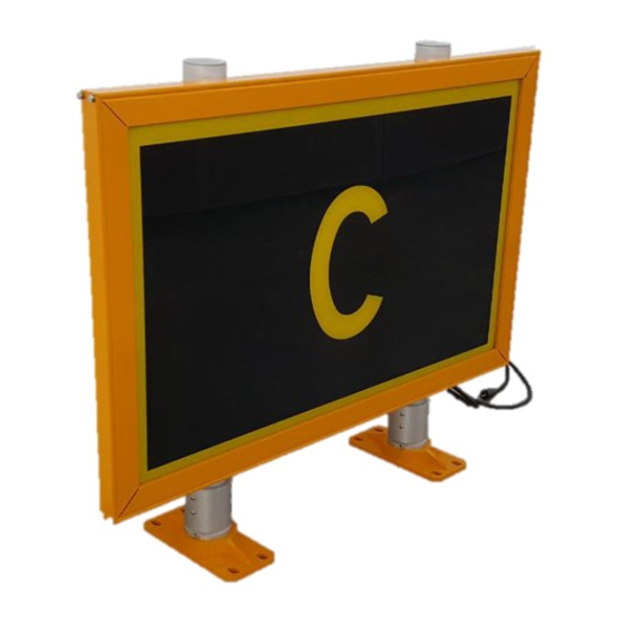
LED LUMINOUS GUIDANCE SIGN
LIMS
INSTRUCTION MANUAL FOR USE, INSTALLATION
AND MAINTENANCE
Compiled by: P. Corinto
Approved by: M. Mazzotti
Via della Solidarietà 2/1 – 40056 Valsamoggia - Italy
THIS COPY IS NOT SIGNED SINCE IT IS FILED AND DELIVERED BY MEANS OF THE AUTOMATIC KNOWLEDGE MANAGEMENT SYSTEM (IT CAN BE SIGNED ON REQUEST). THIS DOCUMENT AND THE DATA CONTAINED HERE IN, IS
PROPRIETARY PROPERTY AND SHALL NOT BE DUPLICATED, USED OR DISCLOSED – IN WHOLE OR IN PART – FOR ANY PURPOSE WITHOUT WRITTEN CONSENT OF OCEM.
Advertisement
Table of Contents

Subscribe to Our Youtube Channel
Related Manuals for OCEM MULTI ELECTRIC LIMS


Summary of Contents for OCEM MULTI ELECTRIC LIMS
- Page 1 THIS COPY IS NOT SIGNED SINCE IT IS FILED AND DELIVERED BY MEANS OF THE AUTOMATIC KNOWLEDGE MANAGEMENT SYSTEM (IT CAN BE SIGNED ON REQUEST). THIS DOCUMENT AND THE DATA CONTAINED HERE IN, IS PROPRIETARY PROPERTY AND SHALL NOT BE DUPLICATED, USED OR DISCLOSED – IN WHOLE OR IN PART – FOR ANY PURPOSE WITHOUT WRITTEN CONSENT OF OCEM.
-
Page 2: Table Of Contents
Document UT-MT-0872-EN Page 2 of 21 Edition 20/01/2017 LIMS INSTRUCTION MANUAL INDEX INDEX ..............................2 INDEX OF FIGURES ..........................3 INDEX OF TABLES ..........................3 GENERAL ......................... 4 CLASSIFICATION OF SIGNS ....................4 Type ..........................4 Legend Sizes ........................4 MAIN FEATURES ...................... -
Page 3: Index Of Figures
Document UT-MT-0872-EN Page 3 of 21 Edition 20/01/2017 LIMS INSTRUCTION MANUAL INDEX OF FIGURES Figure 1: Exploded view ........................5 Figure 2: Frame..........................5 Figure 3: Support ..........................6 Figure 4: Panels ..........................6 Figure 5: LEDs luminous source......................7 Figure 6: Electronic board ......................... -
Page 4: General
Document UT-MT-0872-EN Page 4 of 21 Edition 20/01/2017 LIMS INSTRUCTION MANUAL GENERAL The internally LEDs illuminated LIMS signs are designed to be used on airport taxiways and runways to convey a mandatory instruction, information on a specific location or destination on a movement area or to provide other information to meet the requirements of Surface Movement Guidance. -
Page 5: Main Features
Document UT-MT-0872-EN Page 5 of 21 Edition 20/01/2017 LIMS INSTRUCTION MANUAL MAIN FEATURES Signs Description The signs practically include the following sections (Figure 1): A. Frame B. Supports C. Panels D. LEDs luminous source E. Electronic board Figure 1: Exploded view 3.1.1 Frame The frame principally consists of a bearing bottom structure, two sides and one top... -
Page 6: Supports
Document UT-MT-0872-EN Page 6 of 21 Edition 20/01/2017 LIMS INSTRUCTION MANUAL 3.1.2 Supports Each support includes a pole, a breakable coupling and a floor flange (Figure 3). All components are made of aluminium. The supports are fixed to the structure with “C”... -
Page 7: Leds Luminous Source
Document UT-MT-0872-EN Page 7 of 21 Edition 20/01/2017 LIMS INSTRUCTION MANUAL 3.1.4 LEDs Luminous Source The signs are illuminated by strips LEDs (Figure 5) inserted in suitable supports. High efficiency white LEDs are used, with an average life of 60.000 hours. The positioning of the LEDs has been determined through photometric tests in order to meet the luminance values as... -
Page 8: Models
Document UT-MT-0872-EN Page 8 of 21 Edition 20/01/2017 LIMS INSTRUCTION MANUAL 3.1.6 Models The main sign dimensions are depicted in Figure 7. The possible values for the lengths A, A’, B, C, D and H are indicated in Table 3. Figure 7: Overall dimensions H=300mm B=704mm C=900mm H=400mm B=904mm C=1100mm... -
Page 9: Monitoring Option
Document UT-MT-0872-EN Page 9 of 21 Edition 20/01/2017 LIMS INSTRUCTION MANUAL Three different LED strips are possibly mounted on the signs, according to the overall sign lengths. The correspondence between sign length and LED strip length are showed in Table 4: Strip LEDs Sign length A Quantity... -
Page 10: Part Number Identification
Document UT-MT-0872-EN Page 10 of 21 Edition 20/01/2017 LIMS INSTRUCTION MANUAL Part Number Identification LIMS01 – 3 – 20 – 1 – 01 Basic Part Number: Version: Message Size: 3 = Sign, 300 mm Legend Height 4 = Sign, 400 mm Legend Height Type (visible length mm): 10 = 990 20 = 1950 30 = 2890... -
Page 11: Electrical Data
Document UT-MT-0872-EN Page 11 of 21 Edition 20/01/2017 LIMS INSTRUCTION MANUAL Electrical Data The luminous signs are powered by series circuits through isolating transformers compliant to FAA Specs FAA L830-L831. The power consumption of the LIMS signs are reported in Table 6: for all sign type the power factor is higher than 0.9. -
Page 12: Luminance Data
Document UT-MT-0872-EN Page 12 of 21 Edition 20/01/2017 LIMS INSTRUCTION MANUAL CCR 5 STEP CCR 3 STEP CCR 1 STEP (2.8 A-6.6 A) (4.8 A-6.6) (6.6 A) Type CCR Type Constant Constant Constant Luminance Luminance Luminance Luminance Luminance Levels Levels SINUSOIDAL 100* 100*... -
Page 13: Installation
Edition 20/01/2017 LIMS INSTRUCTION MANUAL NOTE: the electrical and luminous data are referred to constant current regulators and isolating transformers manufactured and/or distributed by OCEM. The data may change with constant current regulators and/or transformers manufactured by other Companies. INSTALLATION a) Take as reference Figure 7 for spacing between breakable couplings. - Page 14 Document UT-MT-0872-EN Page 14 of 21 Edition 20/01/2017 LIMS INSTRUCTION MANUAL alignment and levelling. Do not tighten the flanges anchor nuts, tight (only finger-tight) until the sign installation is complete. Lower the sign with the legs onto the frangible couplings and tight the locking screws. Check the sign to be sure that it is levelled.
-
Page 15: Figure 10: Concrete Foundation
Document UT-MT-0872-EN Page 15 of 21 Edition 20/01/2017 LIMS INSTRUCTION MANUAL Figure 10: Concrete foundation T [mm] Type 3469 3729 3949 4429 4669 4909 5369 Table 10: Foundation sizes... -
Page 16: Maintenance
Document UT-MT-0872-EN Page 16 of 21 Edition 20/01/2017 LIMS INSTRUCTION MANUAL MAINTENANCE ATTENTION! Never operate on electrical and electronic equipment while the CCR is ON. Periodical Checks Daily Check for burned-out led Monthly Check for dirty panels Check for loose wire connections Semi-Annual Check for cracked or deteriorated wires LEDs Luminous Source Replacement... - Page 17 Document UT-MT-0872-EN Page 17 of 21 Edition 20/01/2017 LIMS INSTRUCTION MANUAL d) lift the top cover carefully of a few centimeters and disconnect the earth cable e) remove the top cover f) cut the tie-wraps and disconnect the connector of the damaged LEDs luminous source...
-
Page 18: Electronic Equipment Replacement
Document UT-MT-0872-EN Page 18 of 21 Edition 20/01/2017 LIMS INSTRUCTION MANUAL g) lift the LEDs support and pull the LEDs strip as shown in figure h) Restore the initial condition and turn the main switch to ON position, turn On the CCR and check the correct operation of the sign. -
Page 19: Troubleshooting
Document UT-MT-0872-EN Page 19 of 21 Edition 20/01/2017 LIMS INSTRUCTION MANUAL Troubleshooting Problem Problem cause Solution Defective LED(s) on luminous Replace the LED(s) luminous source(s) source(s) Defective isolating transformer Replace isolating transformer The sign is totally or Defective power supply board Replace power supply board partially not lighted The main switch is left to OFF... -
Page 20: Drawings
Document UT-MT-0872-EN Page 20 of 21 Edition 20/01/2017 LIMS INSTRUCTION MANUAL DRAWINGS Wiring diagram Figure 11: Wiring diagram... -
Page 21: List Of Recommended Spare Parts
Document UT-MT-0872-EN Page 21 of 21 Edition 20/01/2017 LIMS INSTRUCTION MANUAL LIST OF RECOMMENDED SPARE PARTS Article Description 150.4382 F323 power supply board w/o monitoring 1 level 150.4383 F323 power supply board w/o monitoring 2 levels 150.4384 F323 power supply board w/ monitoring 1 level 150.4385 F323 power supply board w/ monitoring 2 levels 150.4390...
Need help?
Do you have a question about the MULTI ELECTRIC LIMS and is the answer not in the manual?
Questions and answers