OCEM LIMS Instruction Manual For Use, Installation And Maintenance
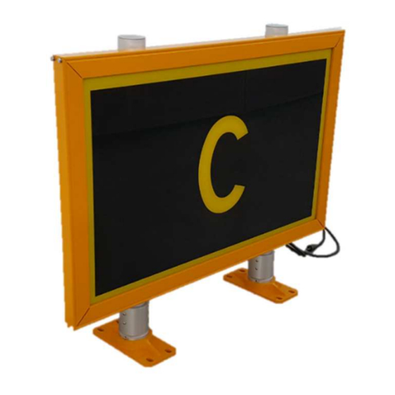
Led luminous guidance sign
Hide thumbs
Also See for LIMS:
Table of Contents
Advertisement
Quick Links
Document UT-MT-0872-EN
Page 1 of 37
Via della Solidarietà, 2/1
40056 Valsamoggia Loc. Crespellano
BOLOGNA ITALY
Edition 08/04/2020
Supersedes edition 27/08/2019
LED LUMINOUS GUIDANCE SIGN
LIMS
INSTRUCTION MANUAL FOR USE, INSTALLATION
AND MAINTENANCE
Compiled by: P. Corinto
Approved by: M. Mazzotti
V. Rossi
Via della Solidarietà 2/1 – 40056 Valsamoggia - Italy
THIS COPY IS NOT SIGNED SINCE IT IS FILED AND DELIVERED BY MEANS OF THE AUTOMATIC KNOWLEDGE MANAGEMENT SYSTEM (IT CAN BE SIGNED ON REQUEST). THIS DOCUMENT AND THE DATA CONTAINED HERE IN, IS
PROPRIETARY PROPERTY AND SHALL NOT BE DUPLICATED, USED OR DISCLOSED – IN WHOLE OR IN PART – FOR ANY PURPOSE WITHOUT WRITTEN CONSENT OF OCEM.
Advertisement
Table of Contents

Subscribe to Our Youtube Channel
Related Manuals for OCEM LIMS


Summary of Contents for OCEM LIMS
- Page 1 THIS COPY IS NOT SIGNED SINCE IT IS FILED AND DELIVERED BY MEANS OF THE AUTOMATIC KNOWLEDGE MANAGEMENT SYSTEM (IT CAN BE SIGNED ON REQUEST). THIS DOCUMENT AND THE DATA CONTAINED HERE IN, IS PROPRIETARY PROPERTY AND SHALL NOT BE DUPLICATED, USED OR DISCLOSED – IN WHOLE OR IN PART – FOR ANY PURPOSE WITHOUT WRITTEN CONSENT OF OCEM.
-
Page 2: Table Of Contents
Document UT-MT-0872-EN Page 2 of 37 Edition 08/04/2020 LIMS INSTRUCTION MANUAL INDEX INDEX ..............................2 INDEX OF FIGURES ..........................3 INDEX OF TABLES ..........................3 GENERAL ......................... 5 CLASSIFICATION OF SIGNS ....................5 Type ..........................5 Legend Sizes ........................5 MAIN FEATURES ...................... -
Page 3: Index Of Figures
Document UT-MT-0872-EN Page 3 of 37 Edition 08/04/2020 LIMS INSTRUCTION MANUAL INDEX OF FIGURES Figure 1: Exploded view ........................6 Figure 2: Frame..........................6 Figure 3: Support ..........................7 Figure 4: Panels ..........................7 Figure 5: LEDs luminous source......................8 Figure 6: Electronic board ......................... - Page 4 Document UT-MT-0872-EN Page 4 of 37 Edition 08/04/2020 LIMS INSTRUCTION MANUAL LIST OF ATTACHMENT Reference n° Document Code Description ABBREVIATIONS AND TERMS Term or abbreviation Description Light Emitting Diode ICAO International Civil Aviation Organization EASA European Aviation Safety Agency Constant Current Regulator...
-
Page 5: General
Surface Movement Guidance. LIMS are single face signs in compliance with ICAO - Annex 14 Vol.1, EASA CS-ADR-DSN Chapter N and NATO-STANAG 3316. White on Red, Yellow on Black and Black on Yellow colour combination may be ordered with any desired message. -
Page 6: Main Features
Document UT-MT-0872-EN Page 6 of 37 Edition 08/04/2020 LIMS INSTRUCTION MANUAL MAIN FEATURES Signs Description The signs practically include the following sections (Figure 1): A. Frame B. Supports C. Panels D. LEDs luminous source E. Electronic board Figure 1: Exploded view 3.1.1 Frame... -
Page 7: Supports
Document UT-MT-0872-EN Page 7 of 37 Edition 08/04/2020 LIMS INSTRUCTION MANUAL 3.1.2 Supports Each support includes a pole, a BREAKABLE COUPLING KIT and a floor flange (Figure 3). All components are made of aluminium. The supports are fixed to the structure with “C”... -
Page 8: Leds Luminous Source
Document UT-MT-0872-EN Page 8 of 37 Edition 08/04/2020 LIMS INSTRUCTION MANUAL 3.1.4 LEDs Luminous Source The signs are illuminated by strips LEDs (Figure 5) inserted in suitable supports. High efficiency white LEDs are used, with an average life of 60.000 hours. - Page 9 Document UT-MT-0872-EN Page 9 of 37 Edition 08/04/2020 LIMS INSTRUCTION MANUAL The main switch MUST BE OPERATED ONLY WITH THE CCR OFF. In general the CCR must be turned off before any intervention on the sign. See Figure 11 and Figure 12 for the two types of wiring diagram of the signs (without and with stabilization circuit).
-
Page 10: Protection Earthing
Document UT-MT-0872-EN Page 10 of 37 Edition 08/04/2020 LIMS INSTRUCTION MANUAL 3.1.6 Protection earthing On the aluminium box containing the electronics, an earthing stud is available (see Figure 6). FOR SAFETY PURPOSES, A CABLE OF 4 MM MINIMUM SECTION, CONNECTED TO THE EARTHING SYSTEM OF THE AGL CIRCUIT MUST BE CONNECTED TO THE EARTHING STUD OF THE SIGN. -
Page 11: Monitoring Option
Document UT-MT-0872-EN Page 11 of 37 Edition 08/04/2020 LIMS INSTRUCTION MANUAL Three different LED strips are possibly mounted on the signs, according to the overall sign lengths. The correspondence between sign length and LED strip length are showed in Table 4:... -
Page 12: Part Number Identification
Document UT-MT-0872-EN Page 12 of 37 Edition 08/04/2020 LIMS INSTRUCTION MANUAL Part Number Identification LIMS01 – 3 – 20 – 1 – 01 Basic Part Number: Version: Message Size: 3 = Sign, 300 mm Legend Height 4 = Sign, 400 mm Legend Height... -
Page 13: Electrical Data
Specs FAA L830-L831 or through a parallel circuit voltage (110-240VAC). The power consumption of the LIMS signs is reported in Table 6. The power factor for the sign is: • higher than 0.8 for all type of signs fed by parallel circuit voltage 110-240VAC;... -
Page 14: Luminance Data
Table 8: Isolating Transformer Size [Watt] with Circuit Stabilizer Luminance Data Two versions of LIMS signs are available, according to the luminance option selected. One luminance level sign: available for both the power supply configurations. The luminance is constant for any value of the series circuit current from 2.8A to 6.6A and the relevant values are shown in Table 9. -
Page 15: Installation
NOTE: for signs powered by a series circuit, the electrical and luminous data are referred to constant current regulators and isolating transformers manufactured and/or distributed by OCEM. The data may change with constant current regulators and/or transformers manufactured by other Companies. -
Page 16: Figure 10: Side By Side Installation (Up), Front Back Installation (Down)
Document UT-MT-0872-EN Page 16 of 37 Edition 08/04/2020 LIMS INSTRUCTION MANUAL j) CONNECT THE EARTHING STUD OF THE SIGN TO THE EARTHING SYSTEM OF THE AGL CIRCUIT THROUGH A CABLE OF AT LEAST 4 MM THE CONNECTION OF THE SIGN EARTHING STUD TO THE AGL EARTHING SYSTEM IS MANDATORY FOR SAFETY PURPOSES. -
Page 17: Figure 11: Foundation
Document UT-MT-0872-EN Page 17 of 37 Edition 08/04/2020 LIMS INSTRUCTION MANUAL Figure 10: Foundation T [mm] Type 3469 3729 3949 4429 4669 4909 5369 Table 10: Foundation sizes... -
Page 18: Option 70 Bird Spikes
Document UT-MT-0872-EN Page 18 of 37 Edition 08/04/2020 LIMS INSTRUCTION MANUAL Option 70 Bird Spikes a) Remove the device from the packaging and clean the back of the device. b) Remove the film from the double-sided adhesive tape. c) Apply the device on the double-sided adhesive by pressing hard. -
Page 19: Maintenance
Document UT-MT-0872-EN Page 19 of 37 Edition 08/04/2020 LIMS INSTRUCTION MANUAL MAINTENANCE ATTENTION! The power supply or CCR MUST be TURNED OFF before any intervention on the sign. Periodical Checks Daily Check for burned-out led Monthly Check for dirty panels... - Page 20 Document UT-MT-0872-EN Page 20 of 37 Edition 08/04/2020 LIMS INSTRUCTION MANUAL d) Lift the top cover carefully of a few centimeters, disconnect the earth cable and remove the top cover. e) Remove the spiral and disconnect the connector of the damaged LEDs luminous source by...
- Page 21 Document UT-MT-0872-EN Page 21 of 37 Edition 08/04/2020 LIMS INSTRUCTION MANUAL f) Cut the tie wrap. g) Lift and rotate the LEDs support and pull the LEDs strip as shown in figure. h) Insert the new strip LEDs in the support, link the wires with a tie wrap and reposition the...
- Page 22 Document UT-MT-0872-EN Page 22 of 37 Edition 08/04/2020 LIMS INSTRUCTION MANUAL i) Reconnect the strip LEDs connector and insert the spiral. j) Connect the earth cable on the top cover and close the sign. Remove the gasket and replace it with a new one.
-
Page 23: Electronic Card Replacement
Document UT-MT-0872-EN Page 23 of 37 Edition 08/04/2020 LIMS INSTRUCTION MANUAL Electronic Card Replacement 5.3.1 Series Circuit Signs a) Be sure that the series circuit is de-activated (CCR OFF); in any case turn the main switch to OFF position. b) Remove the electronic board cover by unscrewing the relevant 4 screws. - Page 24 Document UT-MT-0872-EN Page 24 of 37 Edition 08/04/2020 LIMS INSTRUCTION MANUAL d) Remove the relevant two fixing screws, carefully unstick the left side of the card from the box and pull it. Fixed side e) Paste the thermal-conductive adhesive on the side of the new electronic board and reassemble everything with reverse procedure.
-
Page 25: Parallel Circuit Signs
Document UT-MT-0872-EN Page 25 of 37 Edition 08/04/2020 LIMS INSTRUCTION MANUAL 5.3.2 Parallel Circuit Signs a) Be sure that the power supply is OFF; in any case turn the switch of the sign to OFF position. b) Remove the electronic board cover by unscrewing the relevant 4 screws. - Page 26 Document UT-MT-0872-EN Page 26 of 37 Edition 08/04/2020 LIMS INSTRUCTION MANUAL e) Disconnect all the cable connected on J2 and J3 screw terminal block on the bottom side of the electronic card. f) Unscrew the relevant 4 screws of the electronic card.
- Page 27 Document UT-MT-0872-EN Page 27 of 37 Edition 08/04/2020 LIMS INSTRUCTION MANUAL If it is necessary to replace the driver, proceed with the following procedure: a) Unscrew the 2 fixing screw of the driver. b) Disconnect all the connectors of the driver.
-
Page 28: Front Panel Replacement
Document UT-MT-0872-EN Page 28 of 37 Edition 08/04/2020 LIMS INSTRUCTION MANUAL Front Panel Replacement a) Be sure that the series circuit is de-activated (CCR OFF); in any case turn the main switch to OFF position. b) Follow the instructions up to the point “e” of the paragraph 5.2. - Page 29 Document UT-MT-0872-EN Page 29 of 37 Edition 08/04/2020 LIMS INSTRUCTION MANUAL e) Extract the vertical spacers with the help of a screwdriver using the hole at the top, pushing them inwards and lifting them up f) Extract the old text panel and insert the new one.
- Page 30 Document UT-MT-0872-EN Page 30 of 37 Edition 08/04/2020 LIMS INSTRUCTION MANUAL g) Insert the spacers keeping them adhered to the walls. Be careful not to scratch the panels! 6 cm h) Insert the horizontal spacers with the help of the threaded bars and push them until they touch the lower structure.
-
Page 31: Electronic Equipment Replacement
Document UT-MT-0872-EN Page 31 of 37 Edition 08/04/2020 LIMS INSTRUCTION MANUAL i) Reposition the light-guide panel carefully and the LEDs support on the panels. j) Follow the instructions in the paragraph 5.2 from point “I” to “l” to restore the sign. -
Page 32: Troubleshooting
Document UT-MT-0872-EN Page 32 of 37 Edition 08/04/2020 LIMS INSTRUCTION MANUAL Troubleshooting 5.6.1 Series Signs Problem Problem cause Solution LEDs strip completely open or Replace the LEDs strip. partially short circuited The sign is partially not Plug the LEDs strip connector... -
Page 33: Drawings
Document UT-MT-0872-EN Page 33 of 37 Edition 08/04/2020 LIMS INSTRUCTION MANUAL Varistor burn out Replace the electronic card Electronic card damaged Replace the electronic card LEDs driver malfunction Replace the LED driver Bad connection Check the connections Clean the text panel with a glass... -
Page 34: Figure 13: Wiring Diagram (Series Sign With Circuit Stabilizer)
Document UT-MT-0872-EN Page 34 of 37 Edition 08/04/2020 LIMS INSTRUCTION MANUAL Figure 12: Wiring diagram (series sign with circuit stabilizer) -
Page 35: Wiring Diagram Parallel Signs
Document UT-MT-0872-EN Page 35 of 37 Edition 08/04/2020 LIMS INSTRUCTION MANUAL Wiring diagram parallel signs Figure 13: Wiring diagram (parallel signs powered at 110-230 VAC) -
Page 36: List Of Recommended Spare Parts
RISLT0039 FRONT PANEL L22 H400 with writing RISLT0040 FRONT PANEL L24 H400 with writing RISLT0041 FRONT PANEL L30 H400 with writing RISLT0042 STABILIZER 3.5mH max 20dm LIMS RISLT0043 STABILIZER 7mH da 22dm LIMS RISLT0045 Electronic Card F323 - SESPC0023- power supply board with Monitoring 1/2 levels... -
Page 37: Accessories
Edition 08/04/2020 LIMS INSTRUCTION MANUAL RISLT0046 Driver for Led Strip L=960mm for LIMS L= 10, 20, 30 powered at 230 V RISLT0047 Driver for Led Strip L=1200mm for LIMS L= 13, 24 powered at 230 V RISLT0048 Driver for Led Strip L=720mm for LIMS L= 15, 22 powered at 230 V...
Need help?
Do you have a question about the LIMS and is the answer not in the manual?
Questions and answers