Table of Contents
Advertisement
Quick Links
Montage- und Betriebsanleitung
Mounting and operating instructions
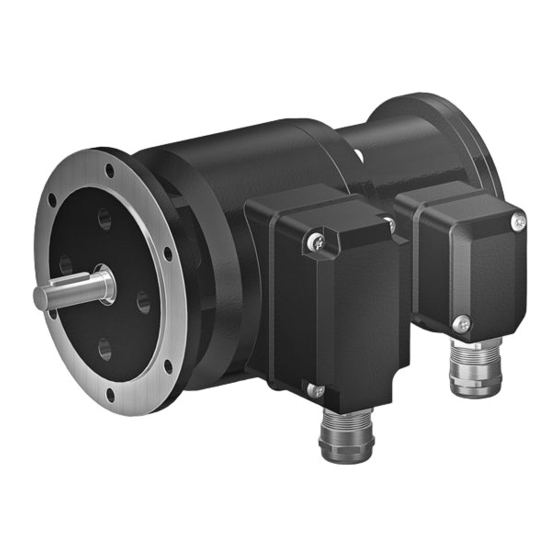
POG 10 + ESL
Kombination
Inkrementaler Drehgeber mit integriertem elektronischen
Drehzahlschalter - EURO-Flansch B10
Combination
Incremental encoder with integrated electronic
speed switch - EURO flange B10
Option M: redundant +
Option EMS: LED
Option EMS: LED
Advertisement
Table of Contents

Related Manuals for Baumer HUBNER POG 10 + ESL


Summary of Contents for Baumer HUBNER POG 10 + ESL
- Page 1 Montage- und Betriebsanleitung Mounting and operating instructions Option M: redundant + Option EMS: LED Option EMS: LED POG 10 + ESL Kombination Inkrementaler Drehgeber mit integriertem elektronischen Drehzahlschalter - EURO-Flansch B10 Combination Incremental encoder with integrated electronic speed switch - EURO flange B10...
-
Page 2: Table Of Contents
Schritt 1 ..................................Schritt 2 ..................................Schritt 3 ..................................Schritt 4 ..................................Maximal zulässige Montagefehler unter Verwendung der Baumer Hübner Federscheibenkupplung K 35 ..................Hinweis bei Verwendung einer Klauenkupplung (zum Beispiel „ROTEX®“) ......Montagehinweis ..............................Abmessung ..................................... Elektrischer Anschluss .............................. - Page 3 Step 2 ..................................... Step 3 ..................................... Step 4 ..................................... Maximum permissible mounting tolerance when the Baumer Hübner K 35 spring disk coupling is used ................. Note when using a jaw-type coupling (for example “ROTEX®”) ........... Mounting instruction ............................. Dimension ....................................
-
Page 4: Allgemeine Hinweise
Gebrauchte Elektro- und Elektronikgeräte dürfen nicht im Hausmüll entsorgt werden. Das Produkt enthält wertvolle Rohstoffe, die recycelt werden können. Wenn immer möglich sollen Altgeräte lokal am entsprechenden Sammeldepot entsorgt werden. Im Bedarfsfall gibt Baumer den Kunden die Möglichkeit, Baumer-Produkte fachgerecht zu entsor- gen. Weitere Informationen siehe www.baumer.com. Achtung! Beschädigung des auf dem Gerät befindlichen Siegels... -
Page 5: General Notes
Whenever possible, waste electrical and electronic equipment should be disposed locally at the authorized collection point. If necessary, Baumer gives customers the opportunity to dispose of Baumer products profession- ally. For further information see www.baumer.com. -
Page 6: Sicherheitshinweise
Sicherheitshinweise Sicherheitshinweise Verletzungsgefahr durch rotierende Wellen Haare und Kleidungsstücke können von rotierenden Wellen erfasst werden. • Vor allen Arbeiten alle Betriebsspannungen ausschalten und Maschinen stillsetzen. Zerstörungsgefahr durch elektrostatische Aufladung Die elektronischen Bauteile im Gerät sind empfindlich gegen hohe Spannungen. • Steckkontakte und elektronische Komponenten nicht berühren. •... -
Page 7: Security Indications
Security indications Security indications Risk of injury due to rotating shafts Hair and clothes may become tangled in rotating shafts. • Before all work switch off all voltage supplies and ensure machinery is stationary. Risk of destruction due to electrostatic charge Electronic parts contained in the device are sensitive to high voltages. -
Page 8: Vorbereitung
Vorbereitung / Preparation Vorbereitung Preparation Lieferumfang Scope of delivery 11 12 Gehäuse POG 10 Housing POG 10 Gehäuse ESL Housing ESL EURO-Flansch B10 EURO flange B10 Vollwelle mit Passfeder Solid shaft with key Klemmenkastendeckel POG 10 Terminal box cover POG 10 Torx-/Schlitzschraube M4x32 mm Torx/slotted screw M4x32 mm Kabelverschraubung M20x1,5 mm Cable gland M20x1.5 mm... -
Page 9: Zur Montage Erforderlich (Nicht Im Lieferumfang Enthalten)
Vorbereitung / Preparation Zur Montage erforderlich Required for mounting (nicht im Lieferumfang enthalten) (not included in scope of delivery) Anbauvorrichtung, kundenspezifisch Installation fitting, customized Befestigungsschrauben M6x16 mm für An- Fixing screws M6x16 mm for installation fit- bauvorrichtung, ISO 4017 ting, ISO 4017 Federscheibenkupplung K 35, Spring disk coupling K 35, als Zubehör erhältlich, siehe Abschnitt 4.5. -
Page 10: Montage
Montage / Mounting Montage Mounting In den Bildern am Beispiel des POG 10 + Pictures showing type standard ESL Standard. Gleiche Montageschritte POG 10 + ESL as example. Same mount- bei allen anderen Versionen. ing steps for all versions. Schritt 1 Step 1 Anzugsmoment: Tightening torque:... -
Page 11: Schritt 3
Montage / Mounting Schritt 3 Step 3 10 mm Schritt 4 Step 4 2.5 mm Anzugsmoment: Tightening torque: = 1.3 ±10 % Nm * Siehe Seite 6 See page 6 MB069.2 - 11055671 Baumer_POG10-ESL_II_DE-EN (19A2) -
Page 12: Maximal Zulässige Montagefehler Unter Verwendung Der Baumer Hübner Federscheibenkupplung K 35
Montage / Mounting Maximal zulässige Montagefehler Maximum permissible mounting toler- unter Verwendung der Baumer Hübner ance when the Baumer Hübner K 35 Federscheibenkupplung K 35 spring disk coupling is used Geräte mit Vollwelle sollten unter Verwen- Devices with a solid shaft should be dung der Baumer Hübner Federschei-... -
Page 13: Hinweis Bei Verwendung Einer Klauenkupplung (Zum Beispiel „Rotex®")
Montage / Mounting Hinweis bei Verwendung einer Klauen- Note when using a jaw-type coupling kupplung (zum Beispiel „ROTEX®“) (for example “ROTEX®”) Eine falsche Montage der Klauenkupplung Incorrect mounting of the jaw-type cou- führt zur Beschädigung des Gerätes. pling can damage the device. Mit einem Tiefenmessschieber die Use a depth gauge to find and observe korrekten Abstände (L, L1), siehe unten,... -
Page 14: Montagehinweis
Abmessung / Dimension Montagehinweis Mounting instruction Wir empfehlen, das Gerät so zu It is recommended to mount the device montieren, dass der Kabelanschluss with cable connection facing down- keinem direkten Wassereintritt ward and being not exposed to water. ausgesetzt ist. Abmessung Dimension (73930, 73935) -
Page 15: Elektrischer Anschluss
Elektrischer Anschluss / Electrical connection Elektrischer Anschluss Electrical connection POG 10 POG 10 6.1.1 Beschreibung der Anschlüsse 6.1.1 Terminal significance Betriebsspannung Voltage supply Masseanschluss 0V ( ) Ground Erdungsanschluss (Gehäuse) Earth ground (housing) Ausgangssignal Kanal 1 Output signal channel 1 Ausgangssignal Kanal 1 invertiert Output signal channel 1 inverted Ausgangssignal Kanal 2 (90°... -
Page 16: Kabelanschluss
Elektrischer Anschluss / Electrical connection POG 10 POG 10 6.1.3 Kabelanschluss 6.1.3 Cable connection 6.1.3.1 Schritt 1 6.1.3.1 Step 1 TX 20 22 mm 6.1.3.2 Schritt 2 6.1.3.2 Step 2 TX 10 * Siehe Seite 5 See page 5 MB069.2 - 11055671 Baumer_POG10-ESL_II_DE-EN (19A2) - Page 17 Elektrischer Anschluss / Electrical connection 6.1.3.3 Schritt 3 und 4 6.1.3.3 Step 3 and 4 ø5...13 mm Ansicht X siehe Abschnitt 6.1.4. Kabelschirm View X Cable shield see section 6.1.4. * Siehe Seite 6 See page 6 Zur Gewährleistung der angegebenen To ensure the specified protection of Schutzart sind nur geeignete Kabel- the device the correct cable diameter...
- Page 18 Elektrischer Anschluss / Electrical connection POG 10 POG 10 6.1.3 Kabelanschluss 6.1.3 Cable connection 6.1.3.4 Schritt 5 6.1.3.4 Step 5 D-SUB Buchse zum Anschluss an das Gerätegehäuse TX 10 siehe Abschnitt 6.1.3.5. D-SUB connector (female) for connecting to the device housing see section 6.1.3.5.
-
Page 19: Klemmenbelegung
Elektrischer Anschluss / Electrical connection 6.1.4 Klemmenbelegung 6.1.4 Terminal assignment 6.1.4.1 Standard 6.1.4.1 Standard Max. 1,5 mm Ansicht X Max. AWG 16 Anschlussklemmen, siehe Abschnitt 6.1.3.3. View X Connecting terminal, see section 6.1.3.3. 0V ( ) Zwischen besteht keine Verbindung. There is no connection between 6.1.4.2 Option EMS... -
Page 20: Option Ems (Enhanced Monitoring System): Status Led / Fehlerausgang
Elektrischer Anschluss / Electrical connection POG 10 POG 10 6.1.5 Option EMS (Enhanced Monitoring 6.1.5 Option EMS (Enhanced Monitoring System): Status LED / Fehlerausgang System): Status LED / Error output Rotblinkend Flash light red Signalfolge-, Nullimpuls- oder Impulszahl- Error of signal sequence, zero pulse or fehler pulses (Fehlerausgang = HIGH-LOW-Wechsel) -
Page 21: Sensorkabel Hek 8 (Zubehör)
Sensorkabel HEK 8 (Zubehör) 6.1.6 Sensor cable HEK 8 (accessory) Es wird empfohlen, das Baumer Hübner Baumer Hübner sensor cable HEK 8 is Sensorkabel HEK 8 zu verwenden oder recommended. As a substitute a shielded ersatzweise ein geschirmtes, paarig ver- twisted pair cable should be used. - Page 22 Elektrischer Anschluss / Electrical connection 6.2.1 Kabelanschluss 6.2.1 Cable connection 6.2.1.2 Schritt 2 6.2.1.2 Step 2 14 * TX 20 Ansicht Y siehe Abschnitt 6.2.2.1 oder 6.2.3.1. Anzugsmoment: View Y Tightening torque: see section 6.2.2.1 or 6.2.3.1. = 2...3 Nm ø5...13 mm Um 180°...
-
Page 23: Esl 90 (1 Internes Relais, 1 Schaltdrehzahl)
Elektrischer Anschluss / Electrical connection 6.2.2 ESL 90 6.2.2 ESL 90 (1 internes Relais, 1 Schaltdrehzahl) (1 internal relay, 1 switching speed) 6.2.2.1 Anschlussbelegung 6.2.2.1 Terminal assignment Ansicht Y Anschlussklemmen, siehe Abschnitt 6.2.1.2. View Y Connecting terminal, see section 6.2.1.2. ≤6 A / 250 VAC ≤1 A / 48 VDC 6.2.2.2... -
Page 24: Esl 93 (3 Relais-Treiber, 3 Schaltdrehzahlen)
Elektrischer Anschluss / Electrical connection 6.2.3 ESL 93 6.2.3 ESL 93 (3 Relais-Treiber, 3 Schaltdrehzahlen) (3 relay driver, 3 switching speeds) 6.2.3.1 Anschlussbelegung 6.2.3.1 Terminal assignment Kabel: Ansicht Y 5-adrig abgeschirmt, Anschlussklemmen, Länge: ≤200 m bei siehe Abschnitt 6.2.1.2. 1 mm Querschnitt View Y Cable:... -
Page 25: 93 R Relaismodul (Zubehör)
Elektrischer Anschluss / Electrical connection 6.2.4 ES 93 R 6.2.4 ES 93 R Relaismodul (Zubehör) Relay modul (accessory) 6.2.4.1 Anschlussbelegung 6.2.4.1 Terminal assignment 3 Kontroll-LED‘s Höhe = 55 mm 3 control LEDs Kunststoffgehäuse für Tragschienenmontage (EN 50022) IP 20 Height = 55 mm 3 Relais/relays Plastic housing for ≤6 A / 250 VAC... -
Page 26: Demontage
Demontage / Dismounting Demontage Dismounting In den Bildern am Beispiel des POG 10 Pictures showing type standard + ESL Standard. Gleiche Demontage- POG 10 + ESL as example. Same dis- schritte bei allen anderen Versionen. mounting steps for all versions. Schritt 1 Step 1 Elektrische Verbindung trennen. - Page 27 Demontage / Dismounting Schritt 2 Step 2 Elektrische Verbindung trennen. Disconnect electrical connection. TX 20 22 mm * Siehe Seite 5 oder 6 See page 5 or 6 MB069.2 - 11055671 Baumer_POG10-ESL_II_DE-EN (19A2)
- Page 28 Demontage / Dismounting Schritt 3 Step 3 10 mm 2.5 mm Schritt 4 Step 4 Schritt 5 Step 5 * Siehe Seite 6 2.5 mm See page 6 MB069.2 - 11055671 Baumer_POG10-ESL_II_DE-EN (19A2)
-
Page 29: Zubehör
Zubehör / Accessories Zubehör Accessories • Federscheibenkupplung • Spring disk coupling K 35 K 35 • Sensorkabel für Drehgeber • Sensor cable for encoders HEK 8 HEK 8 • Werkzeugset: • Tool kit: Bestellnummer 11068265 Order number 11068265 • Digital-Konverter •... -
Page 30: Technische Daten
Montage / Mounting Technische Daten Technische Daten Technische Daten - elektrisch • Störfestigkeit: EN 61000-6-2 • Störaussendung: EN 61000-6-3 Technische Daten - elektrisch (Drehgeber) • Betriebsspannung: 9...30 VDC (HTL-P, TTL - Version R) 5 VDC ±5 % (TTL) • Betriebsstrom ohne Last: ≤100 mA •... -
Page 31: Technische Daten - Mechanisch
Technische Daten - mechanisch • Baugröße (Flansch): ø115 mm • Wellenart: ø11 mm Vollwelle • Zulässige Wellenbelastung: ≤300 N axial ≤450 N radial • Flansch: EURO-Flansch B10 • Schutzart DIN EN 60529: IP66 • Betriebsdrehmoment typ.: 3 Ncm • Trägheitsmoment Rotor: 220 gcm •... -
Page 32: Technical Data
Technical data Technical data Technical data - electrical ratings • Interference immunity: EN 61000-6-2 • Emitted interference: EN 61000-6-3 Technical data - electrical ratings (encoder) • Voltage supply: 9...30 VDC (HTL-P, TTL - version R) 5 VDC ±5 % (TTL) •... -
Page 33: Technical Data - Mechanical Design
Technical data - mechanical design • Size (flange): ø115 mm • Shaft type: ø11 mm solid shaft • Admitted shaft load: ≤300 N axial ≤450 N radial • Flange: EURO flange B10 • Protection DIN EN 60529: IP66 • Operating torque typ.: 3 Ncm • Rotor moment of inertia: 220 gcm •... - Page 34 MB069.2 - 11055671 Baumer_POG10-ESL_II_DE-EN (19A2)
- Page 35 MB069.2 - 11055671 Baumer_POG10-ESL_II_DE-EN (19A2)
- Page 36 Baumer Hübner GmbH P.O. Box 12 69 43 · 10609 Berlin, Germany Phone: +49 (0)30/69003-0 · Fax: +49 (0)30/69003-104 info@baumerhuebner.com · www.baumer.com/motion Version: 73930, 73935 MB069.2 - 11055671 Baumer_POG10-ESL_II_DE-EN (19A2-17.02.2020)
Need help?
Do you have a question about the HUBNER POG 10 + ESL and is the answer not in the manual?
Questions and answers