Advertisement
Quick Links
Advertisement

Related Manuals for STL K-FORCE 27


Summary of Contents for STL K-FORCE 27
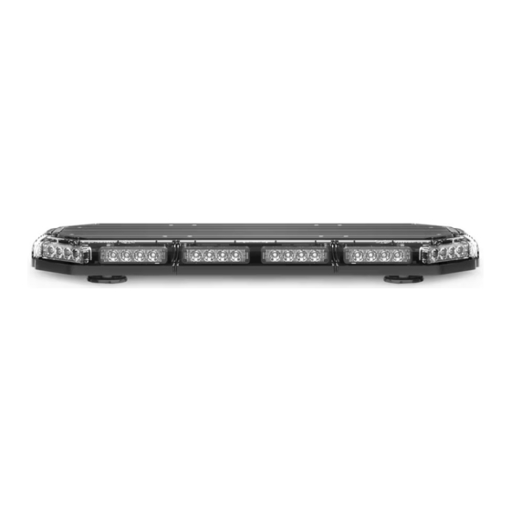
- Page 1 K-FORCE ® MINI LIGHT BAR M-TKF27 M-LKF27 INSTRUCTION MANUAL SpeedTech Lights, Inc © 2019...
- Page 2 This document must be delivered to and read by the end user and installer as it serves to provide you with the required information for proper and safe use of your STL product. Before operating this or any STL products the user and installer must read this manual all the way through. You will find important information in this manual that could prevent property damage and/or serious injury to the user and installer.
-
Page 3: Maintenance
Grommets, cable ties, looms, and other installation hardware should be used to anchor and protect all wiring. Fuses should be properly sized and located as close to the power take off points as possible to protect the wiring and device. To protect against short circuits, a fuse is included by STL for all products. -
Page 4: Specifications
K-FORCE ® MINI LIGHT BAR Wiring Diagram Wire Color Function Wire Color Function Red* Positive White Positive (When bypassing Grand Control Box) Negative No Function Black* Blue Yellow Flash Pattern Green Alley Steady * Indicates a main power cable. NOTE: All cables except Negative contact +12 VDC. NOTE: Connect White and Red cable when bypassing Grand Control box. - Page 5 K-FORCE ® MINI LIGHT BAR Magnet Mounts (Included) • This unit comes included with magnetic mounting brackets pre-attached. • Magnet brackets are adjustable along the length of the aluminum track. • Ensure all four magnets are secured to a flat surface. Stud Mount (Sold Separately) •...
- Page 6 About Flash Patterns • All STL LED products are equipped with a non-volatile memory which will recall the last flash pattern when the Light Bar is turned on. • Set the flash pattern by pushing the Flash Pattern button on the Grand Control Box to cycle through the various patterns.
Need help?
Do you have a question about the K-FORCE 27 and is the answer not in the manual?
Questions and answers