Table of Contents
Advertisement
Quick Links
Advertisement
Table of Contents

Subscribe to Our Youtube Channel
Related Manuals for US Shift Quick 2 GEN2


Summary of Contents for US Shift Quick 2 GEN2
- Page 1 Installation and Operation Manual for 4R70W, 4R75, and AOD-E Transmissions...
- Page 2 State of California to cause cancer or birth defects or other reproductive harm. For more information, visit www.P65Warnings.ca.gov. APPLICATION COVERAGE This system works with all 4R70W, 4R75, and AOD-E automatic transmissions. It is recommended that you use the US Shift wiring harness with this system.
-
Page 3: Table Of Contents
CONTENTS Preparation Page 4 Connecting the Essentials Page 5 Setting up the Quick 2 Page 9 Notes on Installation Page 11 Transmission Diagrams Page 13 Optional Features Page 18 Built-In Display Page 21 Shiftware Page 27 Important Information Page 30 Troubleshooting Error Messages Page 31 Contact... -
Page 4: Preparation
PREPARATION Pre-2001 Transmissions (Originally equipped with a 9-pin solenoid bulkhead connector and "soft wire" internal harness) Before installing the Quick 4 unit, make sure that the transmission has a high impedance (~10 Ohms) torque converter clutch solenoid. A low-impedance solenoid will cause damage to the Quick 4 due to excessive current draw and should never be used. -
Page 5: Connecting The Essentials
CONNECTING THE ESSENTIALS (ELECTRONIC FUEL INJECTION) Step 1: Ground Splice the ground wires (Pins 15 & 16 Black) from the Quick 2 into the main ECU (Engine Control Unit) ground wire. Do NOT connect the ground wires to sheet metal or other ground sources. - Page 6 CONNECTING THE ESSENTIALS (CARBURETED AND MECHANICALLY-INJECTED DIESEL) Step 1: Ground Connect the ground wire (Pin 15 Black) from the Quick 2 directly to the battery ground post or negative battery cable. Do NOT connect the ground wire to sheet metal or other ground sources.
- Page 8 Step 4: Transmission Connectors Connect the Solenoid, PRNDL, and TSS cables to the transmission. Connect the output shaft speed sensor cable to the rear speed sensor, as shown in the illustration. Additionally, connect the Neutral Safety Switch and the Backup Lamp Switch (See page 16).
-
Page 9: Setting Up The Quick 2
SETTING UP THE QUICK 2 Step 6: Calibration Verify that the correct calibration is loaded on the Quick 2. A standard calibration specific to your order is loaded before shipment. However, if the transmission configuration has changed since the order was placed, you'll need to connect the Quick 2 to a Windows PC and install the Shiftware Tuning Software, which can be... - Page 10 If needed, you can manually adjust TPS values by choosing “Adjust Idle” or “Adjust WOT” in the TPS setup menu. Once the TPS calibration procedure is completed, the values are permanently stored in the controller and will be active for every tune written. TPS values displayed within individual tunes are then irrelevant.
-
Page 11: Notes On Installation
NOTES ON INSTALLATION If any error messages or unexpected characters are displayed, refer to the troubleshooting section at the end of this manual for detailed explanations. General Installation The Quick 2 unit should be mounted within the passenger compartment of the vehicle in a protected location. - Page 12 Adaptation for Factory-Equipped Transmissions It is possible to use the Quick 2 controller in a vehicle which was originally equipped with one of the intended transmissions. This could be done in conjunction with an engine management system upgrade that no longer supports the transmission.
-
Page 13: Transmission Diagrams
TRANSMISSION DIAGRAMS... -
Page 18: Optional Features
OPTIONAL FEATURES Speedometer Output We have provided an adjustable speed signal output on the tan wire on pin 12 of the vehicle connector that can be used to drive an electronic speedometer. Use of this output signal is not necessary, but it can be helpful if your speedometer can not be driven correctly from another source. - Page 19 Engine RPM Signal Input The engine RPM signal input on the yellow lead (pin 7) can be connected to a digital tachometer output from an engine computer or the tachometer output from an MSD ignition or similar CDI (Capacitive Discharge Ignition) system, but NEVER to the coil outputs of a CDI system like MSD.
-
Page 21: Built-In Display
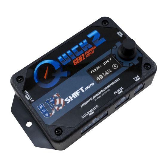
BUILT-IN DISPLAY The second generation built-in display of the Quick 2 is easier to use and more intuitive. It provides useful information, such as current speed, gear, transmission temperature, and TCC lock status, along with any fault messages. Using the menus, you’ll be able to access many of the same options found in Shiftware. - Page 22 Home Screen Normal Mode Home Screen Enlarged Mode...
- Page 23 MAIN MENU Home Screen = Chooses the home screen as your default view. Info Screen = Shows current sensor values, replacing the home screen as default view. Info includes TPS voltage and percentage, battery voltage, commanded pressure in PSI, and engine RPM.
- Page 24 Speed Sensor = This menu allows you to choose your speed sensor type and configure its details such as speedometer drive gear teeth, driven gear teeth, and pulses per revolution. Rotating the knob in this screen changes the speed sensor type. Available speed sensor types will vary depending on the current transmission type.
- Page 25 TUNE MENU Shift Points = Sets the RPM at which shifts occur for all shifts or each individual shift. Once you’ve chosen a shift to adjust, you will be presented with a menu showing 10% throttle, 40% throttle, and Wide Open Throttle. Under each is shown shift point RPM.
- Page 26 Override = There are several options in this menu which are useful when troubleshooting. “Line Prs” can be used to override line pressure manually. Use this only if you were instructed to do so by a Baumann Electronic Controls technician. “TCC Sol”...
-
Page 27: Shiftware
SHIFTWARE Introduction Using the Shiftware software allows you to modify the way your Quick 2 Transmission Control System behaves. You can customize shift-points as well as monitor and diagnose the Quick 2 unit in real-time. Setup To create a calibration for the Quick 2, it is best to start with one of the standard calibrations which are included with the software. - Page 28 Customize The main window is where all of the shift points and line pressure editing is done. The graph displays the up-shift and down-shift speeds in relation to throttle position for each shift. It also displays the line pressure & firmness curve in relation to throttle position.
- Page 29 If Select Pairs Together is enabled, then the corresponding down-shift point will be automatically selected along with the up-shift point. This can be turned off by clicking the checkbox on the right. You can select multiple points by holding CTRL while clicking the points or a range of points by holding SHIFT and clicking the two points on each end.
-
Page 30: Important Information
Writing a Calibration to the Quick 2 For the changes you've made to take effect on the Quick 2 controller, you first must write the calibration to the unit. Connect the Quick 2 to your computer using a standard USB cord (Type A to Type B). Click the Write Calibration button on the toolbar to write the calibration to the controller. -
Page 31: Troubleshooting Error Messages
TROUBLESHOOTING ERROR MESSAGES WARNING! If the transmission does not begin to operate correctly within the first few feet of the road test, STOP immediately, check the troubleshooting guide, and call Baumann Electronic Controls if you need assistance. In some cases, just a few blocks of operation with low fluid pressure can destroy a transmission. - Page 32 EPC (PCS) Solenoid overcurrent error An over-current condition was detected on the line pressure control solenoid. A short circuit may be present in the solenoid circuit. The controller will attempt to disable the solenoid with the over-current condition until the ignition is turned off. Shift Solenoid A (SSA) undercurrent error Current measured on the indicated shift solenoid was too low, indicating that the solenoid circuit may be open.
- Page 33 EPC (PCS) Solenoid circuit shorted Line Pressure Control Solenoid resistance measured too low during the power- on solenoid check. Refer to the data display screen in the diagnostic menu to see the measured solenoid resistance. Shift Solenoid A (SSA) circuit open The indicated Shift Solenoid’s resistance measured too high during the power- on solenoid check.
- Page 34 OSS Circuit Open or Sensor Missing The Output Shaft Speed Sensor circuit is open or the sensor is missing. ISS Circuit Open or Sensor Missing The Input Shaft (Turbine) Speed Sensor circuit is open or the sensor is missing. (if equipped) OSS Sensor Signal Plausibility Error The controller detected an unexpected value from this sensor and marked it as faulty.
- Page 35 Error: PRNDL Signal Low Sensor voltage is low. Error: PRNDL Signal High Sensor voltage is high. Error: No PRNDL PWM Signal Connect the controller to a PC and use Shiftware to reload the calibration using a 4R70W calibration. Error: Invalid PRNDL Code=XX-XX DTR or PSM signal combination not valid.
-
Page 36: Contact
CONTACT If you have any questions, problems, or product orders, don’t hesitate to call our customer service line. (864) 646-8920 (Monday-Friday 10AM-6PM EST). If no one is available, please leave a detailed message and we will reply promptly. Whenever possible, we will try to return urgent technical support calls left after hours or over the weekend. support@usshift.com You can also email customer service at Scan this code to copy the customer service phone number and email address to your phone.
Need help?
Do you have a question about the Quick 2 GEN2 and is the answer not in the manual?
Questions and answers