Sign In
Upload
Download
Table of Contents
Contents
Add to my manuals
Delete from my manuals
Share
URL of this page:
HTML Link:
Bookmark this page
Add
Manual will be automatically added to "My Manuals"
Print this page
×
Bookmark added
×
Added to my manuals
Manuals
Brands
US Shift Manuals
Microphone system
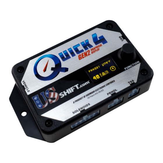
Quick 4 GEN2
Installation and operation manual
US Shift Quick 4 GEN2 Installation And Operation Manual
Graphical display
Hide thumbs
1
2
Table Of Contents
3
4
5
6
7
8
9
10
11
12
13
14
15
16
17
18
19
20
21
22
23
24
25
26
27
28
29
30
31
32
33
34
35
36
37
38
39
40
page
of
40
Go
/
40
Contents
Table of Contents
Troubleshooting
Bookmarks
Advertisement
Table of Contents
1
Table of Contents
2
Connecting the Essentials
3
Setting up the Quick
4
Notes on Installation
5
Transmission Diagrams
6
Optional Features
7
Manual Shift Connections
8
Built-In Display
9
Shiftware
10
Important Information
11
Troubleshooting Error Messages
12
Contact
Download this manual
Installation and Operation Manual for
4L60E, 4L65E, and 4L70E Transmissions
Table of
Contents
Previous
Page
Next
Page
1
2
3
4
5
Advertisement
Table of Contents
Need help?
Do you have a question about the Quick 4 GEN2 and is the answer not in the manual?
Ask a question
Questions and answers
Related Manuals for US Shift Quick 4 GEN2
Microphone system US Shift 4R70W Installation And Operation Manual
(36 pages)
Microphone system US Shift Quick 2 GEN2 Installation And Operation Manual
Graphical display (36 pages)
Microphone system US Shift 4L60E Installation And Operation Manual
Graphical display (40 pages)
Microphone system US Shift 4R100 Installation And Operation Manual
Graphical display (36 pages)
Microphone system US Shift Quick 2 GEN2 Installation And Operation Manual
Graphical display (36 pages)
Microphone system US Shift Quick 6 GEN2 Installation And Operation Manual
Graphical display, ford transmission (44 pages)
Microphone system US Shift Quick4 E4OD Installation And Operation Manual
(44 pages)
This manual is also suitable for:
4l60e
4l65e
4l70e
4l80e
4l85e
Table of Contents
Print
Rename the bookmark
Delete bookmark?
Delete from my manuals?
Login
Sign In
OR
Sign in with Facebook
Sign in with Google
Upload manual
Upload from disk
Upload from URL


Need help?
Do you have a question about the Quick 4 GEN2 and is the answer not in the manual?
Questions and answers