Table of Contents
Advertisement
Quick Links
Advertisement
Table of Contents

Related Manuals for Datcon DT9100 I4

Summary of Contents for Datcon DT9100 I4
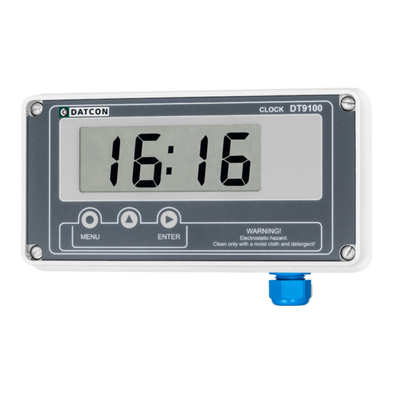
- Page 1 DT9100 I4 Intrinsically Safe Digital Clock Operating Instructions...
-
Page 2: Table Of Contents
DT9100 I4 Contents 1. About this document.............4 1.1. Function..................4 1.2. Target group................4 1.3. Symbolism used................4 2. For your safety..............5 2.1. Authorised personnel..............5 2.2. Appropriate use.................5 2.3. Warning about misuse...............5 2.4. General safety instructions............5 2.5. CE conformity................5 2.6. Safety information for Ex areas..........6 2.7. - Page 3 DT9100 I4 7. Setting up..............28 7.1. Type in the code (password)...........28 7.2. The menu.................29 7.3. Second clear (01. menu item)..........30 7.4. Time-set (02. menu item)............31 7.5. User code (03. menu item)............32 7.6. Synchronisation mode (04. menu item)........34 7.7. Synchronisation time (05. menu item)........35 7.8.
-
Page 4: About This Document
1. About this document 1.1. Function This operating instructions manual has all the information you need for quick set-up and safe operation of DT9100 I4. Please read this manual before you start setup. 1.2. Target group This operating instructions manual is directed to trained personnel. -
Page 5: For Your Safety
2.5. CE conformity The DT9100 I4 is in conformity with the provisions of the following standards: MSZ EN 60079-0:2013 (ATEX) MSZ EN 60079-11:2012 (ATEX) -
Page 6: Safety Information For Ex Areas
DT9100 I4 2.6. Safety information for Ex areas Please note the Ex-specific safety information for installation and operation in Ex areas. These safety instructions are part of the operating instructions manual and come with the Ex-approved instruments. 2.7. Environmental instructions Protection of the environment is one of our most important duties. -
Page 7: Product Description
DT9100 I4 3. Product description 3.1. Delivery configuration Delivered items The scope of delivery encompasses: • DT9100 I4 digital clock • 2 pcs. of srew clamps (only panel mounting version) • 1 pcs. M16x1.5 cable entries • instrument sealing (only panel mounting version) •... -
Page 8: Principle Of Operation
This may be the nearest minute or the nearest hour of the original display or a preset time may be entered during programming. The DT9100 I4 has two isolated digital outputs, which can be used for alarm signaling or for synchronising other clocks. -
Page 9: Adjustment
DT9100 I4 3.3. Adjustment The DT9100 I4 can be adjusted through the 3 front panel membrane keypad. The instrument doesn’t need any internal adjustment. All settings are stored in a battery back-up RAM. At first installation you have to set the time and other working parameters what you need. -
Page 10: Mounting
When mounting DT9100 I4 as panel instrument, use the enclosed seal to assure IP 65 protection between the instrument and the panel on the front side (only for the panel-mounted version). -
Page 11: Main Dimensions Of The Instrument
DT9100 I4 4.2. Main dimensions of the instrument Wall-mounted instrument Panel-mounted instrument 20180905-V1... -
Page 12: Mounting As A Wall-Instrument
DT9100 I4 4.3. Mounting as a wall-instrument Removing the front cover In order to remove the front cover, first remove the four fixing screws as shown in the drawing. A screwdriver of appropriate head-size should only be used. Using screwdrivers with an inappropriate head-size may cause damage to the screws’... - Page 13 DT9100 I4 Preparatory steps There are four through-holes, shown by arrows in the following drawing, for the fastening of the housing. The diameters of the holes are made for M3 screws. Holes for mounting 1. Mark the places of the holes in accordance with the drawing.
- Page 14 DT9100 I4 Mounting the instrument Four M3 threaded screws are needed for mounting the instrument (these are not accessories). The type of the screws depends on the wall-material, while the dimensions cross recessed depend on the wall-thickness. The use of pan head screws is recommended to make the mounting easier.
-
Page 15: Mounting As A Panel-Instrument
DT9100 I4 4.4. Mounting as a panel-instrument Preparatory steps 1. Cut a piece out of the panel according to the figure shown below. The cutting requires special tools; it must be carried out by trained specialist personnel. Cut-out dimensions 20180905-V1... - Page 16 DT9100 I4 Mounting with the screw clamps 2. Put on the enclosed seal onto the instrument case from the rear side and fit it to the instrument holding frame (Figure step 2). 3. Put the instrument into the prepared cut-out as much as possible and check the fitting of the seal between case and mounting surface.
-
Page 17: Connecting
DT9100 I4 and the other instruments (e.g. isolator, Zener barrier). •... - Page 18 DT9100 I4 The DT9100 I4 has a very powerful EMC protection, so grounding and practice on both sides are generally unnecessary, but when a particularly high electrical disturbance device (such as an inverter drive system) is used nearby, it may be necessary to use the above. An important rule is that the signal cables, separate from the power cable.
- Page 19 DT9100 I4 Connecting the cables Make sure before connection that the power supply is into the terminal switched off. assemblies The push-in direct connector assemblies used allow a fast connection of the cables. Their proper usage is shown by the following figure: 1.
-
Page 20: Connecting The Digital Outputs
DT9100 I4 5.2. Connecting the digital outputs A DT9100 I4 digital output is an output for direct driving an other DT910x B clock synchronising input or a NAMUR input. You may connect an instrument to the output which input is in comformity with the following output paremeters: Uo <... -
Page 21: Connecting Into The Current Loop (Synchronising Input)
5.3. Connecting into the current loop (synchronising input) Connecting as end The DT9100 I4 acts as a terminal device of the current loop. device In this case the signal comes via a pair of wires, and it does not have to go to other devices. - Page 22 DT9100 I4 Connecting as “middle” • The DT9100 I4 is situated in the „middle” of the current device loop. In this case one cable comes from the signal source and another cable goes to the next unit(s). The following figure shows the connection:...
- Page 23 DT9100 I4 Finishing steps 1. Check if the cables are connected properly (have you connected all the cables, have you connected them to the right place, are not the cable ends touching each other). 2. Pull back the unnecessary cable length from inside of instrument enclosure.
-
Page 24: Display And Manual Controls
DT9100 I4 6. Display and manual controls 6.1. The first start-up The display The display is indicated by the arrow (1) After the instrument has been installed and connected to the power supply, first you see on the display: ... -
Page 25: Characters And Mnemonics Appearing On The Display
DT9100 I4 6.2. Characters and mnemonics appearing on the display DT9100 I4 has a 7-segment type display. It means that maximum 7 bars are used to form each characters. The numbers can be read easily, some of the letters, marks however, looks unusual: ... - Page 26 DT9100 I4 Messages of critical errors Default factory settings (Service: Default Factory Settings) During code writing Code? (Code) Bad Code (Bad Code) A User login took place (User) A Supervisor login took place (Supervisor) During setting up ...
-
Page 27: Manual Controls
DT9100 I4 6.3. Manual controls DT9100 I4 can be adjusted by the membrane push-buttons indicated by (1), (2), and (3) in the drawing. Functions of the push-buttons during displaying time (1) MENU button: Enters the menu When you push this button, the device will ask for a password (code) in accordance with Chapter 7.1. -
Page 28: Setting Up
DT9100 I4 7. Setting up 7.1. Type in the code (password) The importance of the You may enter the menu only when you type in your code. code The code consists of 4 numbers. This prevents unauthorised access. Levels of authorisation •... -
Page 29: The Menu
DT9100 I4 7.2. The menu The menu structure 01: Second clear 30. page 02: Time set 31. page 03: User code 32. page 04: Synchronisation mode 34. page 05: Synchronisation time 35. page 06: Sync. gate time 36. page 07: Digital output 1 37. -
Page 30: Second Clear (01. Menu Item)
DT9100 I4 7.3. Second clear (01. menu item) Function Set the seconds of time to zero, and round time. If the moment of button pressing the second was between 0 and 29, the hour and minute not changing. If the moment of button pressing the second was between 30 and 59, the minute rounding up (if necessary the hour too). -
Page 31: Time-Set (02. Menu Item)
DT9100 I4 7.4. Time-set (02. menu item) Function Setting the time (hour : minute) without second clearing. Sequence of operations 1. Enter the menu by the user or the supervisor code. The way the code should be typed in can be found in Chapter 7.1. -
Page 32: User Code (03. Menu Item)
DT9100 I4 7.5. User code (03. menu item) Function You can define new codes instead of the factory-defined user code. The code is an optional number within the range between 0000 and 9999. [Default factory setting: 0000] Sequence of operations 1. Enter the menu by typing either the user code or the supervisor code. - Page 33 DT9100 I4 Sequence of operations 9. If the codes written in for the first and second time are identical with each other, the device exits from the menu item. You see this on the display. Do not forget the user code you have specified. If you forget it, defining another one is possible only by using a supervisor code for entering into the menu.
-
Page 34: Synchronisation Mode (04. Menu Item)
DT9100 I4 Synchronisation mode (04. menu item) 7.6. Function Setting the remote synchronisation mode. Sequence of operations 1. Enter the menu by typing the supervisor code. The way the code should be typed in is described in Chapter 7.1. Type in the code (password). You will see this ... -
Page 35: Synchronisation Time (05. Menu Item)
DT9100 I4 Synchronisation time 7.7. (05. menu item) Function Setting remote synchronisation time. When selected in menu item, the clock will set at this time. Sequence of operations 1. Enter the menu by typing in the supervisor code. -
Page 36: Synchronisation Gate Time (06. Menu Item)
DT9100 I4 Synchronisation gate time (06. menu item) 7.8. Function The setting of the pulse width of the remote synchronisation signal. When the active state of the synchronising current is lower then this value the instrument will not accept it as a synchronisation signal (this function is useful for filtering a false value caused by noise). -
Page 37: Digital Output 1 (07. Menu Item)
DT9100 I4 Digital output 1 7.9. (07. menu item) Function Out 1 digital output mode setting. Sequence of operations 1. Enter the menu by typing in the supervisor code. The way the code should be typed in is described in Chapter 7.1. -
Page 38: Digital Output 2 (08. Menu Item)
DT9100 I4 Digital output 2 (08. menu item) 7.10. Function Out 2 digital output mode setting. Sequence of operations 1. Enter the menu by typing in the supervisor code. The way the code should be typed in is described in Chapter 7.1. -
Page 39: Changing The Supervisor Code (09. Menu Item)
DT9100 I4 7.11. Changing the supervisor code (09. menu item) Function You can define new codes instead of the factory-defined supervisor code. The code is an optional number within the range between 0000 and 9999. [Default factory setting: 1000] Sequence of operations 1. Enter the menu by typing in the supervisor code. - Page 40 DT9100 I4 Sequence of operations 9. If the codes type in for the first and second time are identical with each other, the instrument exits from the menu item. You see this on the display. Do not forget the supervisor code you have specified. If you forget it, defining another one is possible in the service only.
-
Page 41: Tests (10. Menu Item)
DT9100 I4 7.12. Tests (10. menu item) Function Checking the display and the limit outputs. Sequence of operations 1. Enter the menu by typing either the user code or the supervisor code. The way the code should be type in is described in Chapter ... - Page 42 DT9100 I4 Sequence of operations 11. If you want to test synchronisation input, press ▲ button to change mnemonic to mnemonic. (It’s meaning: synchronisation input test) 12. Press ENTER button. • 13. You can read on the display:...
-
Page 43: Fault Rectification
In accordance with chapter 2.1. Authorised personnel: For safety and warranty reasons, any internal work on the instrument must be carried out by DATCON personnel. In the case of errors, it is recommended to notice of the displayed error message, as well as of the phenomenon seen. -
Page 44: Appendix
DT9100 I4 10. Appendix 10.1. Technical specifications Intrinsical safety data Certification: BKI 18 ATEX 0007 X Marking: II 2 G Ex ia IIC T6 Ga (-20 °C ≤ Ta ≤ 60 °C) Ex safety data Synchronising input (current loop) 0... - Page 45 DT9100 I4 Environmental conditions: Operating temperature range: -20 °C ≤ Ta ≤ +60 °C Storing temperature range: -25 °C ≤ Ta ≤ +70 °C Klíma osztály: EN 60654-1, class B2 Place of installation: Zone 1, Zone 2, safe area Electromagnetic compatibility (EMC)
-
Page 46: Application Example
DT9100 I4 10.2. Application example 20180905-V120180905... -
Page 47: Error Messages
DT9100 I4 10.3. Error messages The instrument has a sophisticated self-testing function; it is capable of detecting the majority of the errors. All mnemonics (code words) presented on the display come from English expressions in abbreviated forms. The time hasn't been set The time hasn't been set since the first power-up or the clock hasn’t been powered for more then 1 hour. -
Page 48: Messages Of Critical Errors
10.4. Messages of critical errors Such errors are caused normally by structural injuries or damages. Repair is done by the service of Datcon. In case of error it is recommended to notice of the displayed error message, as well as of the phenomenon seen and communicate to the Datcon service personnel. -
Page 49: Description Of The Menu Items
DT9100 I4 10.5. Description of the menu items You find a description of the menu items in the following part. A description on the handling of the menu is in Chapter 7. Setting up. The setting of the time (Sec null) - Page 50 DT9100 I4 Synchronisation time set (Synchron Time) Here you can preset the synchronisation time for the remote Use supervisor synchron function. Code (The seconds are set to zero automatically.) Synchrinisation puls width set (Synchron Gate Time Set) Here you can set the pulse width of the remote Use supervisor synchronisation signal.
- Page 51 DT9100 I4 Changing the Supervisor Code (Supervisor Code) The new Supervisor Code must be typed in twice, in order Use supervisor to avoid any typing errors. The mnemonic (Re- code Type) warns you to type the code for the second time, after you have typed it once.
-
Page 52: Messages And Error Messages During Setting Up
DT9100 I4 10.6. Messages and error messages during setting up The following mnemonics may displayed when the settings are being performed. Exit from the menu, returning to the normal operating mode (Exit) Saving the changed parameters is being done (Save) ... -
Page 53: Setting The Time (Example)
DT9100 I4 10.7. Setting the time (example) Function Time set. Enter the menu 1. Press the MENU button. You will see the mnemonic on the display. The mnemonic will be blinking. 2. You will see: on the display. The left digit will be blinking. - Page 54 DT9100 I4 Setting the hours 9. Press Menu button to escape from menu item. 10. Press the ▲ button to select the menu item. 11. Enter the menu item by pressing the ENTER button. You will see the on the display, and the hours will be blinking.
-
Page 55: Atex Certification
DT9100 I4 10.8. ATEX Certification 20180905-V1... - Page 56 DT9100 I4 20180905-V120180905...
- Page 57 DT9100 I4 20180905-V1...
- Page 58 DT9100 I4 20180905-V120180905...
- Page 59 DT9100 I4 20180905-V1...
- Page 60 DT9100 I4 20180905-V120180905...
- Page 61 DT9100 I4 20180905-V1...
- Page 62 DT9100 I4 20180905-V120180905...
- Page 63 DT9100 I4 20180905-V1...
Need help?
Do you have a question about the DT9100 I4 and is the answer not in the manual?
Questions and answers