Sign In
Upload
Download
Table of Contents
Contents
Add to my manuals
Delete from my manuals
Share
URL of this page:
HTML Link:
Bookmark this page
Add
Manual will be automatically added to "My Manuals"
Print this page
×
Bookmark added
×
Added to my manuals
Manuals
Brands
Yamaha Manuals
Music Mixer
RIVAGE PM5
Owner's manual
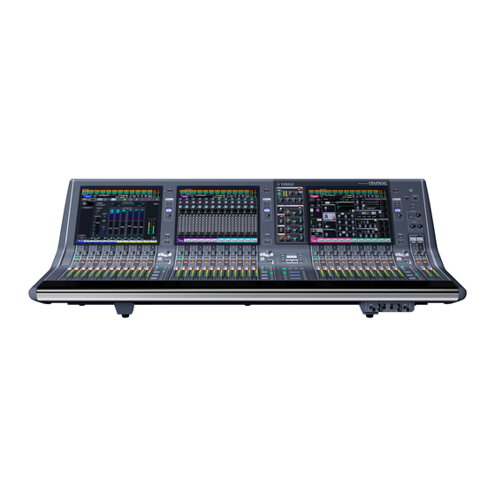
Yamaha RIVAGE PM5 Owner's Manual
Digital mixing systems, control surface
Hide thumbs
1
2
3
4
5
6
Table Of Contents
7
8
9
10
11
12
13
14
15
16
17
18
19
20
21
22
23
24
25
26
27
28
29
30
31
32
33
34
35
36
page
of
36
Go
/
36
Contents
Table of Contents
Troubleshooting
Bookmarks
Table of Contents
Precautions
Table of Contents
Introduction
About Manuals
About Utility Software
Firmware Updates
Conventions in this Manual
Accessories
Part Names & Functions
Top Panel
Front Panel
Rear Panel
Power Supply / Shutdown
Connecting to Power Sources
Shutting down the Power to the Unit
Installing and Removing Optional Cards
Installing a Mini-YGDAI Card
Removing the Mini-YGDAI Card
Touch Screen
Basic Touch Screen Operations
On-Screen User Interface
Viewing a Touch Screen
Other Operations
Initializing the Unit to Factory Default Settings
Adjusting the Faders (Calibration Function)
Troubleshooting
Specifications
General Specifications
Audio Specifications
Input/Output Characteristics
Pin Assignment Table
Dimensional Diagrams
Index
Advertisement
Quick Links
1
Table of Contents
2
Introduction
3
Top Panel
4
Rear Panel
5
Power Supply / Shutdown
6
Basic Touch Screen Operations
7
Other Operations
8
Input/Output Characteristics
Download this manual
CONTROL SURFACE
CS-R5
Owner's Manual
EN
Table of
Contents
Previous
Page
Next
Page
1
2
3
4
5
Advertisement
Table of Contents
Need help?
Do you have a question about the RIVAGE PM5 and is the answer not in the manual?
Ask a question
Questions and answers
Related Manuals for Yamaha RIVAGE PM5
Music Mixer Yamaha RM602 Operating Manual
Yamaha recording mixer operating manual (44 pages)
Music Mixer Yamaha RM602 Operating Manual
Recording mixer (44 pages)
Music Mixer Yamaha RM602 Operating Manual
Recording mixer (44 pages)
Music Mixer Yamaha RM602 Operating Manual
Recoding mixer (44 pages)
Music Mixer Yamaha RM800 User Manual
Yamaha recording mixer user's guide (163 pages)
Music Mixer Yamaha RM800 User Manual
Recording mixer (163 pages)
Music Mixer Yamaha RM1x Quick Start Manual
(6 pages)
Music Mixer Yamaha Ri8-D Owner's Manual
Input/output rack (24 pages)
Music Mixer Yamaha Ro8-D Owner's Manual
Input/output rack (24 pages)
Music Mixer Yamaha Rio1608-D Service Manual
I/o rack (149 pages)
Music Mixer Yamaha RACK Reference Manual
(103 pages)
Music Mixer Yamaha RIVAGE PM7 Systems Setup Manual
Digital mixing console (58 pages)
Music Mixer Yamaha RIVAGE PM Series Supplemental Manual
Digital mixing system (31 pages)
Music Mixer Yamaha RIVAGE PM Series Owner's Manual
Dsp engine for digital mixing system (24 pages)
Music Mixer Yamaha RIVAGE PM10 Operation Manual
(260 pages)
Music Mixer Yamaha RIVAGE PM3 CS-R3 Owner's Manual
Digital mixing system control surface (36 pages)
This manual is also suitable for:
Cs-r5
Table of Contents
Save PDF
Print
Rename the bookmark
Delete bookmark?
Delete from my manuals?
Login
Sign In
OR
Sign in with Facebook
Sign in with Google
Upload manual
Upload from disk
Upload from URL


Need help?
Do you have a question about the RIVAGE PM5 and is the answer not in the manual?
Questions and answers