Table of Contents
Advertisement
Advertisement
Table of Contents

Related Manuals for Yamaha RIVAGE PM3 CS-R3


Summary of Contents for Yamaha RIVAGE PM3 CS-R3
- Page 1 CONTROL SURFACE CS-R3 Owner’s Manual...
- Page 2 ATTENTION RISQUE DE CHOC ELECTRIQUE-NE PAS OUVRIR CAUTION: ATTENTION : TO REDUCE THE RISK OF ELECTRIC SHOCK, POUR RÉDUIRE LES RISQUES D'ÉLECTROCUTION, NE PAS RETIRER DO NOT REMOVE COVER (OR BACK). LE CAPOT (OU LE DOS). NE CONTIENT PAS DE PIÈCES NÉCESSITANT NO USER-SERVICEABLE PARTS INSIDE.
- Page 3 This product contains a battery that contains perchlorate material. Perchlorate Material—special handling may apply, See www.dtsc.ca.gov/hazardouswaste/perchlorate. * This applies only to products distributed by Yamaha Corporation of America. (Perchlorate) Information for users on collection and disposal of old equipment: This symbol on the products, packaging, and/or accompanying documents means that used electrical and electronic products should not be mixed with general household waste.
-
Page 4: Precautions
If you intend to use the product in an area other than in the cord can damage it. one you purchased, the included power cord may not be compatible. Please check with your Yamaha dealer. Location and connection • Check the electric plug periodically and remove any dirt or dust which may have accumulated on it. - Page 5 “No Battery” will appear on the display. In this case, contact avoid data loss or damage. your Yamaha dealer and have qualified Yamaha service personnel replace the backup battery. CS-R3 Owner’s Manual...
- Page 6 • This product contains recyclable components. When disposing of this product, please contact the appropriate local authorities. Yamaha cannot be held responsible for damage caused by improper use or modifications to the product, or data that is lost or destroyed.
-
Page 7: Table Of Contents
Contents PRECAUTIONS......4 Troubleshooting ....29 Introduction ......8 Specifications ......30 About manuals........8 General Specifications ..... 30 About utility software ......9 Audio Specifications ......30 Firmware updates ......9 Input/output Characteristics .... 31 Conventions in this manual....9 Pin Assignment Table ...... 32 Accessories........ -
Page 8: Introduction
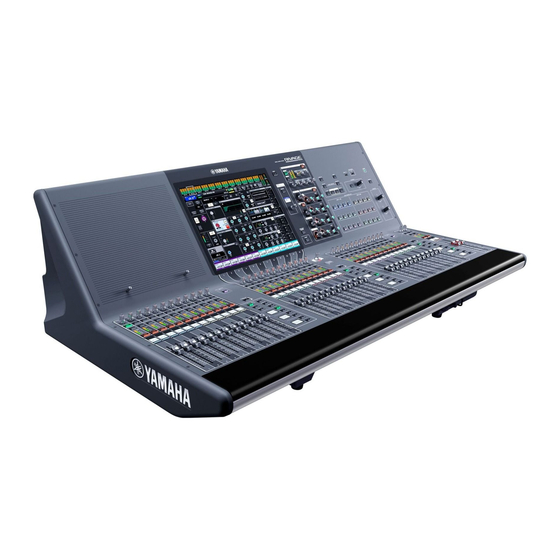
CS-R3. CS-R3. • RIVAGE PM series Operation Manual The CS-R3 is a control surface dedicated to the Yamaha The Operation Manual provides detailed explanations RIVAGE PM series digital mixing system. This manual of all screens and functions, and includes step-by-step... -
Page 9: About Utility Software
• RIVAGE PM StageMix brackets (e.g., SCENE MEMORY [STORE] key). StageMix enables you to use your iPad to wirelessly control the parameters of your Yamaha RIVAGE PM Accessories series digital mixing console. StageMix offers the sound engineer (who is away from the system) the •... -
Page 10: Part Names & Functions
Part Names & Functions Top panel VIEW RANGE RATIO OUTGAIN RECORDING ATTACK HOLD DECAY THRESHOLD OVERLAY UNDO POWER ATTACK RELEASE KNEE ASSIGN UPDATE PREVIEW SCENE MEMORY TALKBACK SYSTEM GAIN STORE RECALL USER DEFINED KEYS MONITOR GAIN BANK BANK GAIN ENCODER ASSIGN GAIN HOME... - Page 11 Selected Channel section This section enables you to adjust parameters for the selected channel. The knobs in the Selected Channel section feature the Touch Sense function. VIEW RANGE RATIO OUTGAIN ATTACK HOLD DECAY RECORDING THRESHOLD ATTACK RELEASE KNEE OVERLAY UNDO POWER ASSIGN UPDATE...
- Page 12 GAIN, HPF, PAN, Fn 1 [GAIN] knob Controls the analog gain or digital gain. 2 HPF [ON] key Switches the HPF on or off. 3 [HPF] knob Adjusts the HPF cutoff frequency. 4 [PAN] knob Adjusts the panning of the signal sent to the stereo buses.
- Page 13 For the latest information on which USB flash drives USER DEFINED KEYS MONITOR GAIN BANK BANK GAIN can be used with the system, visit the Yamaha Pro ENCODER ASSIGN GAIN HOME Audio global website at: TOUCH AND TURN USER DEFINED USER DEFINED http://www.yamahaproaudio.com/...
- Page 14 SCENE MEMORY section 1 [OVERLAY] key Press this button to display the OVERLAY SETTING VIEW RANGE RATIO OUTGAIN ATTACK HOLD DECAY RECORDING THRESHOLD OVERLAY UNDO POWER screen. ATTACK RELEASE KNEE ASSIGN UPDATE PREVIEW SCENE MEMORY TALKBACK SYSTEM GAIN STORE RECALL USER DEFINED KEYS MONITOR While pressing and holding down the [SHIFT] key...
- Page 15 USER DEFINED KEYS section VIEW RANGE RATIO OUTGAIN ATTACK HOLD DECAY RECORDING THRESHOLD OVERLAY UNDO POWER ATTACK RELEASE KNEE ASSIGN UPDATE PREVIEW SCENE MEMORY TALKBACK SYSTEM GAIN STORE RECALL USER DEFINED KEYS MONITOR GAIN BANK BANK GAIN ENCODER ASSIGN GAIN HOME TOUCH AND TURN USER DEFINED...
- Page 16 Touch Screen section (Bay C) Bay C A “bay” consists of a group of 12 faders VIEW RANGE RATIO OUTGAIN located across the Touch Screen section RECORDING ATTACK HOLD DECAY THRESHOLD OVERLAY UNDO POWER ATTACK RELEASE KNEE ASSIGN UPDATE PREVIEW SCENE MEMORY TALKBACK SYSTEM...
- Page 17 Channel Strip section (Bay L, Bay C, Bay R) 1 [ENCODER ASSIGN] key Displays a screen that enables you to switch between VIEW RANGE RATIO OUTGAIN ATTACK HOLD DECAY RECORDING THRESHOLD OVERLAY UNDO POWER the Screen Encoder function and the Channel ATTACK RELEASE KNEE...
- Page 18 6 Strip encoder You can use both the Screen Encoder function and the Channel Encoder function for channel strips 1–12 on bay C. Use the [ENCODER ASSIGN] key (see 1 on page 17) to toggle between these two functions. You can use only the Channel Encoder function for channel strips 1–12 and channel strips A/B on bay L and bay R.
- Page 19 $ INPUT [1]/[2] keys Enable you to select an input layer. Press the INPUT [1] key to select the INPUT 1-72 layer. Press the INPUT [2] key to select the INPUT 73-144 layer. NOTE Press the INPUT [1] key and INPUT [2] key simultaneously to select the INPUT 145-288 layer.
-
Page 20: Front Panel
Front panel 1 PHONES [LEVEL] knob Adjusts the level of the signal output from the PHONES output jack. 2 PHONES output jack This is a headphone jack for monitoring the MONITOR or CUE signal. CS-R3 Owner’s Manual... -
Page 21: Rear Panel
6 OMNI IN jacks These four 4-pin female XLR output jacks are used to These are balanced XLR-3-31 female input jacks for supply power to optional Yamaha LA1L gooseneck inputting analog audio signals from line level devices lamps. or microphones. - Page 22 This indicator lights up or flashes red if an error make sure that you do not block the vent with any occurs. object. In such an event, please contact your Yamaha dealer. The air is taken in through vents at the rear and under the front. @ LINK indicators This indicator flashes or lights up, depending on the network status.
-
Page 23: Power Supply / Shutdown
Power Supply / the unit Shutdown Before you turn off the power to the control surface, Yamaha recommends that you store the current status to scene memory. Connecting to power sources If you change the connection status of the components... -
Page 24: Installing And Removing Optional Cards
Installing a Mini-YGDAI card Before you install the card, you must check the Yamaha Pro Audio global website to see whether your CS-R3 supports that card, and to verify the number of other Yamaha cards or third-party cards that can be used in conjunction with this card. -
Page 25: Touch Screen
List windows Touch Screen Windows similar to the following enable you to select items from a list, such as a list of USER DEFINED keys. Basic touch screen operations This section explains the basic procedures you can perform on the unit’s touch screens. Pressing the touch screen You will use this operation primarily to switch screens and pages, to select the parameter to be operated, and to turn a... -
Page 26: Viewing A Touch Screen
Viewing a touch screen Popup windows When you press a button or field for a specific parameter The following examples describe two types of screens in a screen, a window showing details or a list for that displayed on the touch screens. parameter will appear. -
Page 27: Other Operations
Adjusting the faders Other Operations (Calibration function) Depending on the environment in which you use the Initializing the unit to system, discrepancies may occur in the motion of the motorized faders. You can use the Calibration function to factory default settings correct these discrepancies. - Page 28 If MOTOR DRIVE is selected: If POSITIONING is selected: For the specified faders in the Channel Strip section and For the specified faders in the Channel Strip section and Master section, the motorized fader movement will be Master section, the fader position will be calibrated. automatically calibrated.
-
Page 29: Troubleshooting
❍ Make sure that the power switches are turned ON. ❍ Make sure that the AC power cords are connected. ➥ If the power still does not turn on, contact your Yamaha dealer. The unit is not receiving an audio input signal. -
Page 30: Specifications
Specifications General Specifications Mixing capacity 288 Inputs, 72 MIX + 36 MATRIX + 2 STEREO (DSP-RX-EX) Sampling Internal clock Frequency 44.1 kHz, 48 kHz, 88.2 kHz, 96 kHz frequency Accuracy ±50 ppm Jitter 1.0 ns @Fs=88.2 kHz/96 kHz, 2.0 ns @Fs=44.1 kHz/48 kHz User interface 100 mm touch-sensitive motorized fader (resolution=1024 steps) ×... -
Page 31: Input/Output Characteristics
Dynamic range Input Output Conditions Min. Typ. Max. Unit OMNI IN 1–8 OMNI OUT 1–8 600Ω AD + DA, GAIN: –6 dB — OMNI OUT 1–8 600Ω DA Converter * Dynamic range is measured with an IHF-A filter. Crosstalk (@1kHz) from/to to/from Conditions... -
Page 32: Pin Assignment Table
Control I/O characteristics Terminal Format Level Connector MIDI IN MIDI – DIN 5pin MIDI OUT MIDI – DIN 5pin USB 1–4 USB 2.0 Host USB A (Female) RECORDING USB 2.0 Host USB A (Female) *2 *4 NETWORK [PC] IEEE802.3 10BASE-T/100BASE-TX etherCON CAT5 *3 *4 CONSOLE NETWORK IN/OUT... -
Page 33: Dimensional Diagrams
Approximate Munsell value of exterior color: N5 * The contents of this manual apply to the latest specifications as of the publishing date. To obtain the latest manual, access the Yamaha website then download the manual file. CS-R3 Owner’s Manual... -
Page 34: Index
Index ASSIGN................. 16 Screen encoder..............18 SEL..................18 SEND / USER DEFINED KNOB.......16 SENDS ON FADER .............17 Calibration..............27 SHIFT ................17 Channel encoder............18 Shutting down ..............23 CUE ................18 CUSTOM..............19 Top panel Channel Strip section ..........17 DCA................19 SCENE MEMORY section ........14 Selected Channel section........11 Touch Screen section..........16 ENCODER ASSIGN ........... - Page 35 Yamaha Music Gulf FZE Tel: +356-2133-2093 JAFZA-16, Office 512, P.O.Box 17328, Jebel Ali FZE, Dubai, UAE Tel: +971-4-801-1500 PA54 Head Office/Manufacturer: Yamaha Corporation 10-1, Nakazawa-cho, Naka-ku, Hamamatsu, 430-8650, Japan (For European Countries) Importer: Yamaha Music Europe GmbH Siemensstrasse 22-34, 25462 Rellingen, Germany...
- Page 36 Yamaha Pro Audio global website http://www.yamahaproaudio.com/ Yamaha Downloads https://download.yamaha.com/ Manual Development Group © 2020 Yamaha Corporation Published 06/2020 IPTO-A0 VDM9540...
Need help?
Do you have a question about the RIVAGE PM3 CS-R3 and is the answer not in the manual?
Questions and answers