AGS Merlin 1000S Installation & Operation Manual
Gas utility isolation controller
Hide thumbs
Also See for Merlin 1000S:
- Installation & operation manual (12 pages) ,
- Installation operation & maintenance (12 pages) ,
- User & installation manual (10 pages)
Table of Contents
Advertisement
Quick Links
Installation & Operation Manual
Merlin 1000S
Merlin 1000S
Gas Utility Isolation Controller
Installation & Operation Manual
Please read this manual carefully and retain for future use.
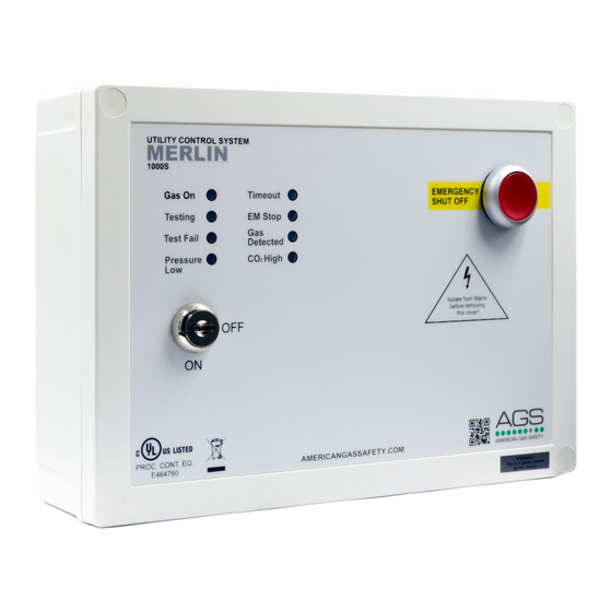
The Merlin 1000S gas pressure proving and detection system is designed specifically for use in
educational establishments and laboratories. The system is designed to give full control over
incoming gas supply with the lockable main key-switch and touch sensors.
1000S IOM Rev: 07
01-20
1
Advertisement
Table of Contents

Related Manuals for AGS Merlin 1000S


Summary of Contents for AGS Merlin 1000S
- Page 1 Installation & Operation Manual Please read this manual carefully and retain for future use. The Merlin 1000S gas pressure proving and detection system is designed specifically for use in educational establishments and laboratories. The system is designed to give full control over incoming gas supply with the lockable main key-switch and touch sensors.
-
Page 2: Table Of Contents
Installation & Operation Manual Merlin 1000S Contents INSTALLATION ................... 3 Planning ........................... 3 Fixing - Mounting ......................3 Typical Installation Arrangement ................4 Terminal Connections ....................4 Switch Settings........................ 7 Specification ........................9 OPERATION ....................10 First Power Up ....................... 10 Emergency Shut Off Button .................. -
Page 3: Installation
The Merlin 1000S is designed to give the teacher full control over the incoming gas supply with the lockable main key-switch and touch sensors. -
Page 4: Typical Installation Arrangement
Installation & Operation Manual Merlin 1000S Typical Installation Arrangement Terminal Connections 1. POWER / LINE IN 110-120V AC Power should be supplied to the [POWER / LINE IN] terminal and fused at 3A. On connecting the mains supply to the panel the power LED indicator will light up – this is located on the front cover (American Gas Safety Logo). - Page 5 Connections for remote emergency shut-off or stop buttons is detailed on the circuit board as [EM REMOTE]. This is linked out as a factory setting. Remote emergency shut-off buttons should be volt free and wired to the Merlin 1000S using a plenum security cable, white, 18/2 (18AWG 2 conductor), stranded, CMP or similar.
- Page 6 Installation & Operation Manual Merlin 1000S 7. FAN SWITCHES This terminal switches when the key is turned on and off. This can be connected to a fan switch (supplied separately) which can provide power to fans when the control panel is switched on.
-
Page 7: Switch Settings
Installation & Operation Manual Merlin 1000S Switch Settings There are various dip-switches on the front circuit board that can be adjusted to configure your system as per the following. Auto Reset There is a switch located on the circuit board labelled [AUTO RESET]. - Page 8 Once the settings have been changed - remove power for 10 seconds. Fire Panel Integration The Merlin 1000S can be integrated with a fire alarm to close the gas supply automatically in the event of a fire. The volt free fire alarm signal can be wired in series with any remote emergency shut off buttons.
-
Page 9: Specification
Installation & Operation Manual Merlin 1000S Specification Model: 1000S Visual Indication Mains Electrical Power Input 100-120VAC Gas Solenoid Valve Output 100-120VAC Current Consumption 12W max or 50mA @ 120VAC Internal Fuse 3.15A Operating Temperature 32 – 104°F 0-95%RH Non-Condensing Audible Alarm Buzzer dB... -
Page 10: Operation
Gas On When the key switch is turned on, the Merlin 1000S will check the installation for gas leaks. If gas proving is successful, the gas valve will open and the ‘Gas On’ LED will illuminate. ON = Gas On OFF = Gas Off ... - Page 11 Installation & Operation Manual Merlin 1000S Test Fail Under normal working conditions this LED is off. When the panel detects a gas leak on start-up, the LED will illuminate AMBER. Gas valve will remain closed. OFF = OK ON = gas proving failed.
-
Page 12: Servicing & General Maintenance
Installation & Operation Manual Merlin 1000S Servicing & General Maintenance It is recommended that any detectors connected to the system are inspected and serviced at least annually from the date of installation for optimum performance and protection. DO carefully remove any accumulated dust from the outer enclosure once a month. -
Page 13: Important Warning Statements
Installation & Operation Manual Merlin 1000S IMPORTANT WARNING STATEMENTS Please take the time to thoroughly read this user’s guide which should be retained for future reference. It is recommended that this device be commissioned upon installation. Do not apply lighter gas or other aerosols to detectors – this will cause extreme damage to the gas sensing elements. - Page 14 Installation & Operation Manual Merlin 1000S Notes 1000S IOM Rev: 07 01-20...
- Page 15 Installation & Operation Manual Merlin 1000S Notes 1000S IOM Rev: 07 01-20...
-
Page 16: Installation Details
Installation & Operation Manual Merlin 1000S Installation Details Please pass this manual to the system owner or system user. Date of Installation: Installation Location: Organisation: Stamp/ Signature of the installer: CONTACT US: AGS Head Office Tel: (727) 608-4375 Fax: (727) 538-4237 info@americangassafety.com...
Need help?
Do you have a question about the Merlin 1000S and is the answer not in the manual?
Questions and answers