KVM-TEC Smartline SVX1 User Manual
Hide thumbs
Also See for Smartline SVX1:
- Manual (8 pages) ,
- Quick manual (3 pages) ,
- User manual (70 pages)

Related Manuals for KVM-TEC Smartline SVX1


Summary of Contents for KVM-TEC Smartline SVX1
- Page 1 Check out our Installation Channel: kvm-tec User Manual Smartline SVX 6501 SET 6501L CPU/LOCAL 6501R CON/REMOTE kvm-tec = C www.kvm-tec.com connect collaborate communicate control...
-
Page 2: Table Of Contents
3.3 Viewing the current firmware version 4.1 Access to Network Settings menu (Master View and Network Mode) 3.4 Updating a firmware 4.2 Disconnect or select a workstation from the current 3.4.1 Updating with bitmap image connected devices 2 | kvm-tec kvm-tec | 3... - Page 3 TABLE of CoNTENTS kvm-tec = C 4.3 ManagIng user details rights and Groups 4.4 Managing the remote units 4.5 Managing local units connect collaborate communicate control 4.6 Installing dual-head or multi-head system 4.7 Enable user groups and rights and login access 4.8 Auto-connect to a free computer after an interruption...
-
Page 4: Introduction
These instructions are part of this product. They contain important WARNING! Read and understand all safety instructions. information regarding safety, use and disposal for every user of the Smartline SVX1 KVM Extender. Please familiarise yourself with the information within prior to using your product. Use the product •... -
Page 5: Technical Specifications
DANGER! Never touch the adapter with wet hands. • Use the product within the specified performance limits. Model: Smartline SVX1 KVM Extender • Keep the product away from flammable materials such as curtains and drapes. • Protect the mains adapter from use by third parties (particularly children). Keep the unused Power supply input voltage: 100 - 240 V;... -
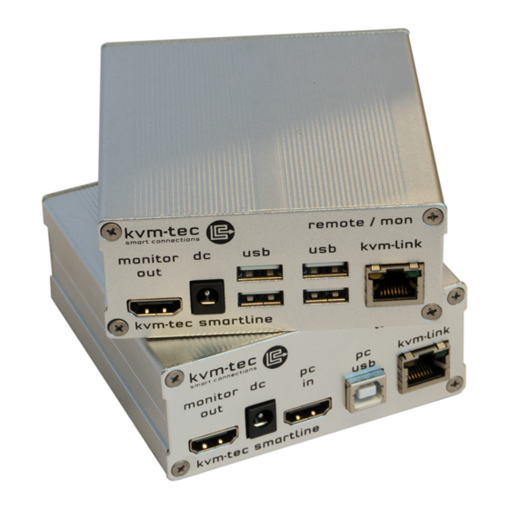
Page 6: Product Elements
KVM-Link/ RJ45 socket Connection for CAT5/6/7 cable PC USB USB connection to PC Power/Status LED Displays the status of the extender KVM-Link/ RJ45 socket Connection for CAT5/6/7 cable Power/Status LED Displays the status of the extender 10 | kvm-tec kvm-tec | 11... -
Page 7: About The Status Led
1 x Power supply 12V; 1A EU plug or INT plug RJ45 Socket LEDs * 1 x DVI -HDMI cable 1,8m / 5.9ft 4 x Mounting Pads Yellow Yellow Slow Green Green V. fast * MVX only ** Rem. only 12 | kvm-tec kvm-tec | 13... -
Page 8: Installation Of The Extender
The following mounting kits are available: Rack Mounting Kit RMK-F - Part No. 6130 The rack mounting kit RMK-F is for assembling kvm-tec Smartline SVX and Masterline MVX extenders. It consists of 19“ rack shelf and an alu-faceplate. Rack Mounting Kit RMK-FN - Part No. 6131 The rack mounting kit RMK-FN is for assembling kvm-tec Smartline SVX and Masterline MVX extenders. - Page 9 CPU / Local Unit (PC-in). Then connect the monitor with the hDMI-DVI cable to the CoN / Remote Unit. HAVE FUN - your kvm-tec Extender is now in use for many years ( MTBF approx 10 years) 2.
-
Page 10: Start Up
3. To access a sub-menu press the applicable key. 2.5 REMOVINg A CATx CABLE To remove a CATx cable: • Press the latch down and slowly pull the cable out. 18 | kvm-tec kvm-tec | 19... -
Page 11: System Status
The enabled options and the current fW-version is displayed in the left top corner. Link status shows whether there is a physical connection available. Connection indicates if kvm data is currently able to be transmitted. Video and USB show if data is currently being transmitted. 20 | kvm-tec kvm-tec | 21... -
Page 12: Updating A Firmware
3.4.1 UpDATINg WITh BITMAp IMAgE The file is output from an image and saved in the currently connected extenders. The latest version of the firmware can be downloaded from http://www.kvm-tec.com/en/ support/firmware-download.html. Each update file is accompanied by a detailed description of the update process. -
Page 13: Performing An Autoupdate
As soon as all updates have been transmitted, the marked devices can be The flashing of the light emitting diodes indicates when the update process is finished (the restarted and start with the new firmware. light emitting diodes are then green) 24 | kvm-tec kvm-tec | 25... -
Page 14: Unlock An Upgrade
7. To confirm the upgrade has been unlocked return to the Options Overview menu and 3. Press 1 to enable or 0 to disable the USB Memory upgrade. check that the relevant upgrade is now displayed in green. 26 | kvm-tec kvm-tec | 27... -
Page 15: Defining What Ddc Data Your Pc Uses
5. Press the buttons 4 to 8 to use a predefined resolution, the is stored in the memory. 6. Press ESC to return to the main menu. 3.8 ChANgINg ThE NETWORk sETTINgs see chapter „Switching Menu settings“. 28 | kvm-tec kvm-tec | 29... -
Page 16: Changing The Usb Compatibility Mode
1. from the Extender Settings menu, press the L key. The Local Settings menu appears. 2. Press the U key to enable or disable the USB compatibility mode. • Press the R button to display the Remote Settings menu. 30 | kvm-tec kvm-tec | 31... -
Page 17: Show Last Received Image
1. from the Extender Settings menu, press the R key. The Remote Settings menu appears. 2. Press the I key to enable or disable the function. 3. Press ESC to go back to the main menu. 32 | kvm-tec kvm-tec | 33... -
Page 18: Locking Main Menu
2. Press the L key. The Menu Lock Menu appears. 2. Press the P key to enable or disable the power saving mode. 3. When in power saving mode, press any key to return to the menu. 34 | kvm-tec kvm-tec | 35... -
Page 19: Selecting A Keyboard Layout
1. from the Extender Settings menu, press the R key. The Remote Settings menu appears. 2. Press the K key. The Keyboard Locale menu opens: • Press E to select English (QWERTY) • Press D to select German (QWERTZ) • Press F to select French (AZERTY) 36 | kvm-tec kvm-tec | 37... -
Page 20: Editing Keyboard Shortcuts
You can manually logout by pressing the “x” key or disconnect from the 3.9.9 CLOsINg ExTENDER sETTINgs MENU current PC by pressing the „d“ key. To close the Extender Settings menu: • Press Q to close the Extender Settings menu. 38 | kvm-tec kvm-tec | 39... -
Page 21: Sharing Videos
If the selected local extender currently isn‘t connected, a regular connection including USB, etc. is established. 40 | kvm-tec kvm-tec | 41... -
Page 22: Disconnect Or Select A Workstation From The Current Connected Devices
Settings menu (Master View and Network Mode)”). function. Some modes require others, and others are incompatible with each other, but the system will automatically recognise this for you. Press the M key to access the Network Mode menu. 42 | kvm-tec kvm-tec | 43... -
Page 23: Managing User Details Rights And Groups
• Press the D key to force disconnect the selected device/connection. • Press the E key or Enter key to select a PC or workstation to create or break a connection to that unit. • Press the Q key to exit. 44 | kvm-tec kvm-tec | 45... - Page 24 • Master: May interrupt connections of Users. In the case that a Master interrupts the connection of another Master, the interrupted Master may reclaim the original connection. Admins and private connections can’t be interrupted. 46 | kvm-tec kvm-tec | 47...
-
Page 25: Managing The Remote Units
(Master View and Network Mode)”). 3. To edit the name of an extender, press the I key. The Console Extender Detail menu opens. 4. Press the E key to edit the name of the extender. 48 | kvm-tec kvm-tec | 49... -
Page 26: Managing Local Units
Team B PC: Group 3 Alex, Blair and Charlie are assigned to be members of Group 1 and Group 2. Danny, Em and frankie are assigned to be members of Group 1 and Group 3. 50 | kvm-tec kvm-tec | 51... -
Page 27: Installing Dual-Head Or Multi-Head System
4. Press the A key to add individual extenders. The extender type is automatically determined once the first extender has been selected. 5. Press the E key to edit the multi-head set name of max. 16 characters. 52 | kvm-tec kvm-tec | 53... -
Page 28: Enable User Groups And Rights And Login Access
Master View and Network Mode“). Settings menu (Master View and Network Mode)”). 2. Press the C key to disable or enable the option. 2. Press the P key to disable or enable the option. 54 | kvm-tec kvm-tec | 55... -
Page 29: Installing A Private Connection
3. To establish a private connection, hold down the Shift key while selecting a new connection (you can either press 4 or press a key combination) - see chapter - „Switching between two PCs“. 56 | kvm-tec kvm-tec | 57... -
Page 30: Enable The Disconnect On Pc Power Down Option
To enable the PC Power Down option: 1. Make sure the Network Mode menu is open (see chapter „how to access the switching menu Master View and Network Mode“). 2. Press the D key to disable or enable the option. 58 | kvm-tec kvm-tec | 59... -
Page 31: Reconnect On Startup
See chapter „how to switch between different computers“. • T – Time in min: You define the number of minutes since the last switch before the user and password details are required again to switch. 60 | kvm-tec kvm-tec | 61... -
Page 32: Troubleshooting & First Aid
Unit have the correct firmware firmware LED is lighting The screen flickers, Install current firmware from our homepage www.kvm-tec.com/ Check if local and remote Unit have the green has an incorrect support/firmware-download same firmware... -
Page 33: Requirements For Cables
• The shield should be contiguous and connected to both ends. A shielded patch cable is allowed for connection to the device. Schema EIA/TIA-568 B Color Orange/White Orange Green/White Blue Blue/White Green Brown/White Brown 64 | kvm-tec kvm-tec | 65... -
Page 34: Maintance & Care , Disposal
This symbol on the product, the accessories or packaging indicates that this product must A list of kvm-tec tested and recommended switches can be found on our website at not be treated as unsorted municipal waste, but must be collected separately! Dispose of the product via a collection point for the recycling of waste electrical and electronic equipment www.kvm-tec.com... -
Page 35: Warranty & Extended Warranty
9. WARRANTY & EXTENDED WARRANTY 10. CoNTACT ADDRESS If you have any questions about our products, please contact kvm-tec or your dealer. Warranty lasts 24 months from the date of purchase. The defect product has to be sent back to the manufacturer or your supplier within 2 weeks. -
Page 36: Notes
11. NoTES 70 | kvm-tec...
Need help?
Do you have a question about the Smartline SVX1 and is the answer not in the manual?
Questions and answers