KVM-TEC Smartline Dual SVX2 Series User Manual
Smart connections
Hide thumbs
Also See for Smartline Dual SVX2 Series:
- User manual (36 pages) ,
- Quick instruction (2 pages)

Related Manuals for KVM-TEC Smartline Dual SVX2 Series


Summary of Contents for KVM-TEC Smartline Dual SVX2 Series
- Page 1 USER-MANUAL SVX2 Smartline Dual smart connections Smartline Dual SVX2 6502 SET 6501L CPU/LOCAL 6501R CON/REMOTE Check out our Installation Channel:...
-
Page 2: Table Of Contents
2.2.2 Mounting kits (optional) 2.3 Installing the extender 2.4 start up 2.5 Removing a catx cable 3.1 Access the main menu 3. Extender menu/settings 3.2 status Menu 3.3 Viewing the current firmware version 3.4 Updataing a firmware 2 | kvm-tec... - Page 3 3.9.4 Locking the main menu 3.9.5 Using the power saving mode 3.9.6 Selecting a keyboard layout 3.9.7 Changing the keyboard fallback mode 3.9.8 Editing keyboard shortcuts 3.9.9 Closing the Extender Settings menu 3.10 Switching between different computers 3.11 sharing videos kvm-tec | 3...
- Page 4 4.8 auto-connect to a free computer after an interruption 4.9 Installing a private connection 4.10 enable the User-Pc binding mode 4.11 enable the disconnect on Pc Power Down option 4.12 Hidding system status menu 4.13 Reconnect on startup 4.14 set the password timeout 4 | kvm-tec...
- Page 5 5. troubleshooting & first aid 6. Requirements for cables 6.1 Requirements for cat5e/6/7 cables 7. Requirements network switch 8. Maintance & care , Disposal 9. Warranty 9. Contact adress 10. notes kvm-tec | 5...
-
Page 6: Introduction
In these user instructions the smartline sVX2 KVM extender is referred to as ‘product’ or ‘extender‘. the sVX2/Pc is referred to as the ‘local unit / cPU and the sVX1/Monitor is referred to as the ‘remote unit‘/con. 6 | kvm-tec... -
Page 7: Safety Instructions
• The product must be connected to a permanent and earthed AC wall socket. • Protect cables from being strained, pinched or buckled and place them in a way to prevent people from tripping over the cord. kvm-tec | 7... - Page 8 Unplug all connections before cleaning the product. Do not use wipes or chemicals as these could damage the surface. Wipe the housing with a damp cloth. Electrical/ electronic parts must not be cleaned. • Alterations to the product and technical modifications are not permitted. 8 | kvm-tec...
-
Page 9: Technical Specifications
Anodized aluminum Dimensions: approx. 198 x 41 x 103,5 mm / 7.79 x 1.57 x 4.07” Weight: Local 604g/1.33lbs Remote 582g/1,28 lbs Shipment weight Set 2,45kg / 4.96 lbs Expected product life: 82 820 hours / 9.5 years kvm-tec | 9... -
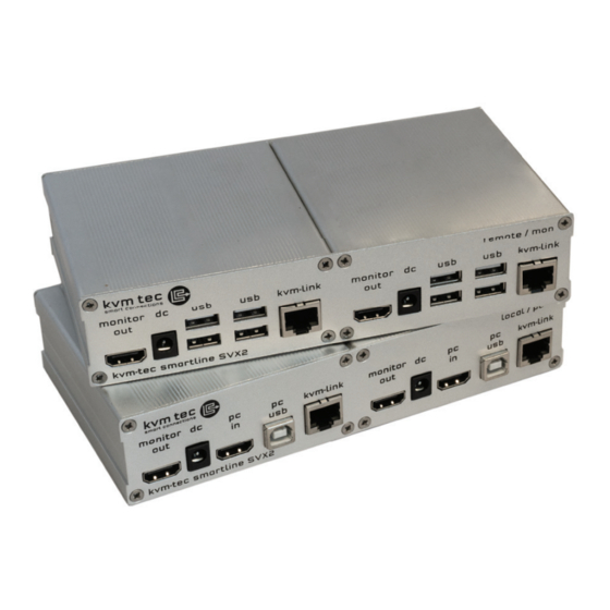
Page 10: Product Elements
Monitor out connection to monitor connection for 12 V power supply DVI From PC Videosingal from PC Pc Usb Usb connection to Pc KVM Link/Rj45 socket Connection for CAT5e/6/7 cable Power/status leD Displays the status of the extender 10 | kvm-tec... - Page 11 Displays the status of the extender Monitor out connection to monitor Connection for 12 V power supply Usb connection (e.g. for keyboard or mouse) KVM link/ RJ45 socket connection for cat5e/6/7 cable Power/status leD Displays the status of the extender kvm-tec | 11...
-
Page 12: About The Status Led
Main lEd Update failed slow orange orange fast Update in Progress Green Update succedded Green V. fast Yes** Red/Green V. fast rJ45 Socket lEds * Yellow Yellow slow Green Green V. fast * MVX only ** Rem. only 12 | kvm-tec... -
Page 13: Unpacking And Checking The Contents
2 x USB cable 1,8m/5.9ft 4 x Mounting Pads remote/Con Unit 1x sVX2 remote/con extender 1 x Power supply 12V; 1a eU plug or Int plug 2 x DVI -HDMI cable 1,8m / 5.9ft 4 x Mounting Pads kvm-tec | 13... -
Page 14: Mounting Options
The following mounting kits are available: Rack Mounting Kit RMK-f - Part no. 6130 the rack mounting kit RMK-f is for assembling kvm-tec smartline sVX and Masterline MVX extenders. It consists of 19“ rack shelf and an alu-faceplate. Rack Mounting Kit RMK-fn - Part no. 6131 the rack mounting kit RMK-fn is for assembling kvm-tec smartline sVX and Masterline MVX extenders. -
Page 15: Installing The Extender
In the case of the latter, an additional Network Switch must be installed. With a Network Switch, each user can gain quick access to any of the required computers. point to point connection Set up with swtching System up to 48 endpoints kvm-tec | 15... - Page 16 4. DVI out to Monitor 2. USB from Kayboard and Mouse 4. DVI out to Monitor 2. USB to PC 4. DVI out to Monitor 2. USB to PC 4. DVI in from PC 4. DVI out to Monitor 16 | kvm-tec...
- Page 17 / local Unit (Pc-in). then connect the monitor with the HDMI-DVI cable to the con / Remote Unit. HAVE FUN - your kvm-tec Extender is now in use for many years ( MTBF approx 10 years) kvm-tec | 17...
-
Page 18: Start Up
2. InstallatIon of tHe eXtenDeR 2.5 rEMoVInG a CaTX CablE To remove a CaTx cable: • Press the latch down and slowly pull the cable out. 18 | kvm-tec... -
Page 19: Access The Main Menu
1. Make sure the extenders, the monitors and the computer are switched on. 2. Press the Scroll lock key on your keyboard quickly fi ve times. The main menu appears with an overview of the sub-menus. 3. to access a sub-menu press the applicable key. kvm-tec | 19... -
Page 20: Status Menu
The enabled options and the current FW-version is displayed in the left top corner. link status shows whether there is a physical connection available. connection indicates if kvm data is currently able to be transmitted. Video and Usb show if data is currently being transmitted. 20 | kvm-tec... -
Page 21: Viewing The Current Firmware Version
3.3 VIEWInG ThE CUrrEnT FIrMWarE VErSIon To view the fi rmware version: • Make sure the main menu is open. The currently installed fi rmware versions of the remote and local units are displayed below (e.g. ‘4267’) kvm-tec | 21... -
Page 22: Updataing A Firmware
3. eXtenDeR MenU/settInGs UodaTInG a FIrMWarE The latest version of the fi rmware can be downloaded from http://www.kvm-tec.com/en/ support/fi rmware-download.html. Each update fi le is accompanied by a detailed description of the update process. you have 3 possibilitiese for an update... -
Page 23: Updating With Bitmap Image
The fi le is output from an image and saved in the currently connected extenders. Wait until all 3 phases of the update have been completed and make sure that you do not disconnect or plug in the devices during the update. kvm-tec | 23... -
Page 24: Performing An Autoupdate
As soon as the devices are connected, the fi rmware is copied from one unit to the other. The fl ashing of the light emitting diodes indicates when the update process is fi nished (the light emitting diodes are then green) 24 | kvm-tec... -
Page 25: Performing A Network Update
During this process the devices can still be in operation. as soon as all updates have been transmitted, the marked devices can be restarted and start with the new fi rmware. kvm-tec | 25... -
Page 26: Unlock An Option
5. enter the unlock code your supplier provided. 6. the extender will automatically restart. 7. To confi rm the Option has been unlocked return to the options overview menu and check that the relevant upgrade is now displayed in green. 26 | kvm-tec... -
Page 27: Enable Or Disable The Usb Memory Upgrade
1. Make sure the main menu is open. 2. Press the M key. the options overview menu opens. the current Usb Memory status is displayed (enabled or Disabled). 3. Press 1 to enable or 0 to disable the Usb Memory upgrade. kvm-tec | 27... -
Page 28: Defining What Ddc Data Your Pc Uses
5. Press the buttons 4 to 8 to use a predefi ned resolution, the is stored in the memory. 6. Press ESC to return to the main menu. 3.8 ChanGInG ThE nETWorK SETTInGS see chapter „Switching Menu settings“. 28 | kvm-tec... -
Page 29: Changing Extender Settings
To access the Extender Settings menu: 1. Make sure the main menu is open. 2. Press the G key. the Extender Settings menu appears. 3. the extender settings are distributed across two sub-menus: remote Settings and local Settings. kvm-tec | 29... - Page 30 3. eXtenDeR MenU/settInGs 4.. View the local or remote extender settings: • Press the l button to display the local setting menu. • Press the r button to display the Remote settings menu. 30 | kvm-tec...
-
Page 31: Changing The Usb Compatibility Mode
Usb compatibility mode can be enables or disabled. To enable/disable the USb compatibility mode: 1. from the Extender Settings menu, press the l key. the local Settings menu appears. 2. Press the U key to enable or disable the Usb compatibility mode. kvm-tec | 31... -
Page 32: Show Last Received Image
To enable or disable the last Image received function: 1. from the Extender Settings menu, press the r key. the remote Settings menu appears. 2. Press the S key to enable or disable the function. 3. Press ESC to go back to the main menu. 32 | kvm-tec... -
Page 33: Turning On Or Off Monitor Synchronization
To turn on monitor synchronization: 1. from the Extender Settings menu, press the r key. the remote Settings menu appears. 2. Press the I key to enable or disable the function. 3. Press ESC to go back to the main menu. kvm-tec | 33... -
Page 34: Locking The Main Menu
The extender menu can be locked. When enabled, the extender locks 5 minutes after start up to prevent unauthorized access. To lock or unlock the menu: 1. from the Extender Settings menu, press the r key. the remote Settings menu appears. 2. Press the l key. the Menu lock Menu appears. 34 | kvm-tec... -
Page 35: Using The Power Saving Mode
1. from the Extender Settings menu, press the r key. the remote Settings menu appears. 2. Press the P key to enable or disable the power saving mode. 3. When in power saving mode, press any key to return to the menu. kvm-tec | 35... -
Page 36: Selecting A Keyboard Layout
1. from the Extender Settings menu, press the r key. the remote Settings menu appears. 2. Press the K key. the Keyboard locale menu opens: • Press E to select English (qWERTY) • Press d to select German (qWERTZ) • Press F to select French (AZERTY) 36 | kvm-tec... -
Page 37: Changing The Keyboard Fallback Mode
To change the keyboard fallback mode: 1. from the Extender Settings menu, press the r key. the remote Settings menu appears. 2. Press the o key to change the keyboard fallback mode to 0, 1 or 2. kvm-tec | 37... -
Page 38: Editing Keyboard Shortcuts
• Press a single key. Edit the frequency with left and right arrows. - oR - • Press a key combination 3.9.9 CloSInG EXTEndEr SETTInGS MEnU To close the Extender Settings menu: • Press Q to close the Extender Settings menu. 38 | kvm-tec... -
Page 39: Switching Between Different Computers
• If the password system is active, the user currently logged in is displayed at the bottom. You can manually logout by pressing the “x” key or disconnect from the current PC by pressing the „d“ key. kvm-tec | 39... -
Page 40: Sharing Videos
If the selected local extender currently isn‘t connected, a regular connection including Usb, etc. is established. 40 | kvm-tec... -
Page 41: Access The Network Settings Menu
To access the network Settings menu (Master View and network Mode): 1. Make sure the main menu is open (see chapter „How to access the main menu“) 2. Press the W key. the Enter User/Password window opens. kvm-tec | 41... -
Page 42: Network Mode
You may have more than one selected depending on their function. some modes require others, and others are incompatible with each other, but the system will automatically recognise this for you. Press the M key to access the network Mode menu. 42 | kvm-tec... -
Page 43: Disconnect Or Select A Workstation From The Current
To force disconnect or select a workstation from the current connected devices: 1. Make sure the Master View menu is open (see chapter „How to access the network Settings menu (Master View and Network Mode)”). kvm-tec | 43... - Page 44 • Press the d key to force disconnect the selected device/connection. • Press the E key or Enter key to select a Pc or workstation to create or break a connection to that unit. • Press the Q key to exit. 44 | kvm-tec...
-
Page 45: Managing User Details, Rights And Groups
To manage user details, rights and groups: 1. Make sure the Master View menu is open (see chapter „How to access the network Settings menu (Master View and Network Mode)”). kvm-tec | 45... - Page 46 2. Press the U key. the User list menu opens. • Press the a key to add a new user. • Press the r key to delete the selected user. • Press the I key to display details about the selected user which may be edited. 46 | kvm-tec...
- Page 47 Private connections can’t be interrupted. • Master: May interrupt connections of Users. In the case that a Master interrupts the connection of another Master, the interrupted Master may reclaim the original connection. admins and private connections can’t be interrupted. kvm-tec | 47...
-
Page 48: Managing Remote Units
To view the status of all remote/Con extenders: 1. Make sure the Master View menu is open (see chapter „How to access the network settings menu (Master View and Network Mode)”). 48 | kvm-tec... - Page 49 • “free” indicates that this extender is not busy. 3. to edit the name of an extender, press the I key. the Console Extender detail menu opens. 4. Press the E key to edit the name of the extender. kvm-tec | 49...
-
Page 50: Managing Local Units
Status aller lokal Units (CPU) 1. Make sure that the Master View menu is open (see chapter „network settings - Master and Network Mode“). 2. Press the P key to open the Pc extender list (cPU) menu. 50 | kvm-tec... - Page 51 Pc: Group 2 team b Pc: Group 3 alex, blair and charlie are assigned to be members of Group 1 and Group 2. Danny, em and frankie are assigned to be members of Group 1 and Group 3. kvm-tec | 51...
-
Page 52: Installing Dual-Head Or Multi-Head System
Individual grouping of local (CPU) and remote (CON) extenders: 1. Make sure that the Master View menu is open (see chapter „Network - Networking“). Settings - „Master View and Network Mode“) 2. Press M. The Multi Head confi guration menu opens. 52 | kvm-tec... - Page 53 4. Press the a key to add individual extenders. the extender type is automatically determined once the fi rst extender has been selected. 5. Press the E key to edit the multi-head set name of max. 16 characters. kvm-tec | 53...
-
Page 54: Enable User Groups And Rights And Login Access
To enable the password option: 1. Make sure the network Mode menu is open (see chapter „How to access the network Settings menu (Master View and Network Mode)”). 2. Press the P key to disable or enable the option. 54 | kvm-tec... -
Page 55: Auto-Connect To A Free Computer After An Interruption
To enable the auto-connect option: 1. Make sure the network Mode menu is open (see chapter „How to access the switching menu Master View and Network Mode“). 2. Press the C key to disable or enable the option. kvm-tec | 55... -
Page 56: Installing A Private Connection
2. Press V to enable or disable the option. 3. to establish a private connection, hold down the Shift key while selecting a new connection (you can either press 4 or press a key combination) - see chapter - „Switching between two PCs“. 56 | kvm-tec... -
Page 57: Enable The User-Pc Binding Mode
To enable the User-PC binding mode: 1. Make sure the network Mode menu is open (see chapter „How to access the switching menu Master View and Network Mode“). 2. Press the b key to disable or enable the option. kvm-tec | 57... -
Page 58: Enable The Disconnect On Pc Power Down Option
To enable the PC Power down option: 1. Make sure the network Mode menu is open (see chapter „How to access the switching menu Master View and Network Mode“). 2. Press the d key to disable or enable the option. 58 | kvm-tec... -
Page 59: Hidding System Status Menu
To hide the info display during startup: 1. Make sure the network Mode menu is open (see chapter „How to access the switching menu Master View and Network Mode“). 2. Press the h key to disable or enable the option. kvm-tec | 59... -
Page 60: Reconnect On Startup
1. Make sure the network Mode menu is open (see chapter „How to access the switching menu Master View and Network Mode“). 2. Press the T key to disable or enable the option. 4.14 VIDeo sHaRInG See chapter „How to share videos“. 60 | kvm-tec... -
Page 61: Set The Password Timeout
See chapter „How to switch between different computers“. • T – Time in min: You defi ne the number of minutes since the last switch before the user and password details are required again to switch. kvm-tec | 61... -
Page 62: Troubleshooting & First Aid
Establish microphone connection: plug stereo-jack to the microphone input of the PC (pink) connection with local oUt lEd is lighting The screen flickers, Install current firmware from our homepage www.kvm-tec.com/ green has an incorrect support/firmware-download display Error... - Page 63 Unit is causing the problem by swaping fi rst the local and than the remote Unit to ano- check if other units have ther Unit the same behaviour contact kvm-tec contact kvm-tec support support kvm-tec | 63...
-
Page 64: Requirements For Cables
Only use shielded installation cable with min. cross section of 24 AWG throughout the length. • The shield should be contiguous and connected to both ends. A shielded patch cable is allowed for connection to the device. Schema EIa/TIa-568 b Color orange/White orange Green/White blue blue/White Green brown/White brown 64 | kvm-tec... -
Page 65: Requirements Network Switch
The network switch must fulfil the following specifications: 1 Gigabit Switch, with true port to port transfer rates of 1 Gigabit/second The following switches have all been tested and verified to work with all features of kvm-tec electronic’s sVX smartline and MVX Masterline KVM-extenders. - Page 66 6146 NS24SFP/4SFP+ Network Switch 24x SFP/4x SFP+ 6166 NS48SFP/4SFP+ Network Switch 48 x SFP/4x SFP+ with redundancy power supply 6151 Network Switch 32 x SFP/2x qSFP+ NS32SFP+/2qSFP+ 6161 NS48SFP+/4qSFP+ Network Switch 48x SFP+ 10G / 4x qSFP+ 66 | kvm-tec...
-
Page 67: Maintance & Care , Disposal
| 67... -
Page 68: Warranty
• Damage by lightning Always contact us first before sending back the product. 2 years standard warranty Part nr 9003 Warranty extension to 5 years per UNIT Part nr 9002 Warranty extension to 5 years per SET 68 | kvm-tec... -
Page 69: Contact Adress
1o. contact aDRess If you have any questions about our products, please contact kvm-tec or your dealer. kvm-tec electronic gmbh Gewerbepark Mitterfeld 1a 2523 tattendorf austria Phone: 0043 (0) 2253 81 912 Fax: 0043 (0) 2253 81 912 99 email: support@kvm-tec.com Web: www.kvm-tec.com... -
Page 70: Notes
11. nIotes 70 | kvm-tec...
Need help?
Do you have a question about the Smartline Dual SVX2 Series and is the answer not in the manual?
Questions and answers