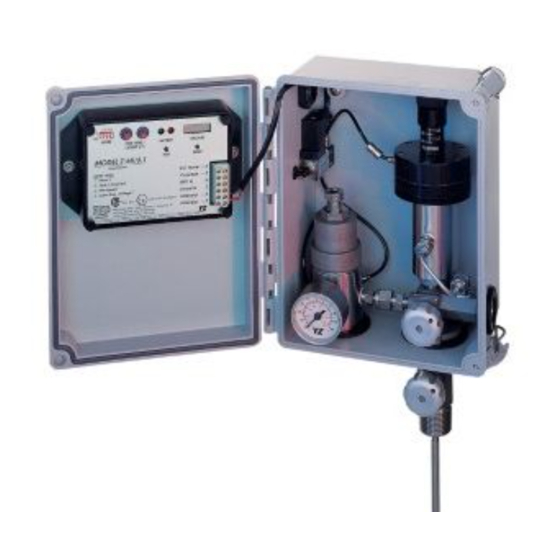
YZ Systems DynaPak 2010 Series System Support Manual
Hide thumbs
Also See for DynaPak 2010 Series:
- System support manual (40 pages) ,
- System support manual (38 pages) ,
- System support manual (34 pages)
Table of Contents
Advertisement
Quick Links
Advertisement
Table of Contents

Related Manuals for YZ Systems DynaPak 2010 Series


Summary of Contents for YZ Systems DynaPak 2010 Series
- Page 1 DynaPak 2010RL System Support Manual Version 01242005...
-
Page 2: Table Of Contents
Table Of Contents 1. Introduction 2. System Components 3. Theory of Operation 4. Sampler Location 5. Sampler Installation 6. Sample Vessel Installation 7. Operational Check & Leak Testing 8. Sampler Set-Up: time-based sampling 9. Sampler Set-Up: time-based sampling with the DPS-2 10. -
Page 3: Introduction
1. Introduction Congratulations on your purchase of the DynaPak 2010 Series Sampler. You've made a wise measurement investment for your company. Before you begin installation, insure that all of the necessary components are present. You will need a sample cylinder(s) during the installation. If you have questions concerning installation/operation, contact your YZ representative or YZ Customer Service at 936.788.5593. -
Page 4: Theory Of Operation
3. Theory of Operation DynaPak 2010 Gas Sampler C. Proportional-to-flow sampling: The DynaPak 2010 Sampler is a remote mounted in this mode of operation, the Z-65 counter system which uses the pneumatically operated, operates as a dividing counter. The Z-65 counter positive displacement DynaPak 2000 pump, the periodically energizes a low power solenoid valve. -
Page 5: Sampler Location
4. Sample Location 4.1 The sampler should be connected to the pipeline utilizing a sample probe at a point a minimum of five pipe diameters from any device which could cause aerosols or significant pressure drops. 4.2 The sampler probe should not be located within the defined meter tube region (AGA 3 manual). -
Page 6: Sampler Installation
5. System Installation **CAUTION Incorrect operation of valves (over tightening) can result in damage to the valve components (isolation valve bonnet assembly) which might result in the valve stem being screwed out of the probe body. This of course results in product at pipeline pressure being vented continually through this port until this section of the pipeline is shut in. - Page 7 5. System Installation 5.2 Optional DPS-2: a. With the low pressure supply valve and the high pressure supply valve closed, connect the DPS-2 to the orifice connection tubing. b. Open the equalization valve. Black c. Open the low pressure supply valve or the high pressure supply valve.
-
Page 8: Sample Vessel Installation
6. Sample Vessel Installation 6.1 Variable pressure/constant volume cylinders. Spun cylinders may be installed in a horizontal position on the DynaPak BackRack vessel rack. Avoiding traps in the line, install stainless steel tubing and fittings from the sample discharge port of the sampler to the product end of the sample cylinder. -
Page 9: Operational Check & Leak Testing
7. Operational Check & Leak Testing 7.1 When all of the tubing connections have been completed, close the purge valve on the front of the sampler probe body. Open the sample probe supply valve to allow pipeline pressure into the sampler. Check all connections using a liquid leak detector. -
Page 10: Sampler Set-Up Time-Based Sampling
8. Sampler Set-Up Time-based sampling 8.1 Calculate the sampling rate using the following 30 day chart: Number of turns sample Sample cylinder volumes open on pump pump stroke knob displacement 1000 cc 300 cc 500 cc per stroke .100 .200 Sample rate (minutes) - Page 11 8. Sampler Set-Up Time-based sampling 8.3 Adjust the pump volume adjustment knob to the value used in the calculations in step 8.1. Sample pump displacement per stroke Number of turns open on the pump volume knob .1cc .2cc .4cc Factory Mutual System Approved...
-
Page 12: Sampler Set-Up Time-Based Sampling With The Dps-2
9. Sampler set-up time-based sampling with the DPS-2 9.1 Calculate the sampling rate using the following 30 day chart: Number of turns sample Sample cylinder volumes open on pump pump stroke knob displacement 1000 cc 300 cc 500 cc per stroke .100 .200 Sample... - Page 13 9. Sampler set-up time-based sampling with the DPS-2 9.3 Adjust the pump volume adjustment knob to the value used in the calculations in step 9.1. Sample pump displacement per stroke Number of turns open on the pump volume knob .1cc .2cc .4cc Factory...
-
Page 14: Sampler Set-Up Proportional-To-Flow Sampling
10. Sampler set-up proportional-to-flow sampling In this mode of operation, the Z-65 controller is used as a dividing counter to control the rate at which the pump is actuated. The desired time between pump strokes is controlled by the host computer or output device that will give an input pulse to the Z-65 controller. - Page 15 10. Sampler set-up proportional-to-flow sampling 10.4 Calculate the counter setting using the following chart: 1. your pump displacement (from .1 to .4cc’s) a.__________ 2. your sample cylinder volume in cc’s (300cc, 500cc, etc.) b.__________ 3. average flow rate (MMCF per day or MCM per day) c.__________ 4.
-
Page 16: Sampler Maintenance
11. Sampler maintenance 11.1 Recommended preventative maintenance schedule Every sampling situation is unique. Below are our f. Remove the diaphragm housing from the pump recommendations for average conditions. A body by unscrewing the diaphragm housing and higher BTU content will necessitate more frequent carefully pulling the plunger out of the pump body. - Page 17 11. Sampler maintenance g. Remove the internal bushings and o-rings from the pump body by inserting a nonmetallic rod (larger than 1/4", smaller than 1/2") into the top of the pump body. Gently tap to remove all bushings and o-rings out the bottom of the pump body. h.
- Page 18 NOTE: Follow the illustration to assure proper battery wire placement in the Z-65 enclosure. 5. Return the mode switches to their original positions. Battery Pack 6. Send your depleted battery to: YZ Systems, Inc. 206 Lubbock Hwy. Snyder, TX 79549 USA...
- Page 19 11. Sampler maintenance 11.4 Recommended spare parts for the DynaPak 2000 Series gas samplers. Part Number Description Qty. Location C4-0004 Filter element see diagrams #3 and #4 D3-0002 DP-2000 pump seal kit see diagrams #1 and #2 D3-0003 YZ filter regulator repair kit see diagrams #3 and #4 D3-0142 Z-65/200 fuse replacement kit...
-
Page 20: Troubleshooting
12. Troubleshooting Timer Mode 12.1 Mechanical Operation Test: A. Set the mode switches as follows: 1. Positions 1, 2 and 3 on. 2. Position 4 off. B. Set the time switches to 00 to enter the diagnostic mode. This mode enables the user to increase the solenoid output rate to one pulse every two seconds. - Page 21 12. Troubleshooting Timer Mode E. This will cause all six digits to become active on the stroke counter. Depress the reset. The stroke counter should increment 000000, 111111, etc., up to 999999 each time the solenoid fires. When the counter display reads 999999, the test is complete.
- Page 22 12. Troubleshooting Timer Mode 12.4 Timer Range Setting 2. Z-65/6.03 Range Setting: a. x.x minutes: set the configuration jumper to the far left position (factory setting). b. .xx minutes: set the configuration jumper to the center position. Note: To obtain maximum battery life, choose the Factory Mutual System...
- Page 23 12. Trouble Shooting Counter Mode 12.5 Input Pulse Test A. Set the mode switches as follows: 1. Position 1 and 3 on, 2 and 4 off. B. Set the count switches to 00 to enter the diagnostic mode. This mode enables the user to determine if the proper input pulses are being Factory Mutual...
-
Page 24: Diagrams
Diagram #1: DP 2000 pump (assembled) -
Page 25: Dp-2000 Pump (Exploded)
Diagram #2: DP 2000L pump (exploded) Set Screw *Seal P/N C0-0096 P/N A6-0018 Spring Retainer Bushing Volume Adjustment Knob P/N B1-0011 P/N B1-0002 O-Ring (010) Discharge Check Valve Spring P/N A5-1010 P/N C3-0007 Cap Screw (6 Each) Discharge Check Valve Sleeve P/N C0-0014 P/N B1-0014 ume Adjustment Detent... -
Page 26: Yz Filter Regulator (Assembled)
Diagram #3: YZ filter/regulator (assembled) -
Page 27: Yz Filter Regulator (Exploded)
Diagram #4: YZ filter/regulator (exploded) Adjustment Screw P/N A3-0066 O-Ring (214) * P/N A5-1214 Pneumatic Body Fitting P/N A3-0074 P/N A1-0113 Pneumatic Fitting P/N A1-0113 Bonnet P/N A3-0067 Tubing Fitting Spring Cap P/N A1-0117 P/N A3-0068 Pressure Gauge P/N A8-0016 Piston Spring O-Ring (120) * P/N C3-0009... -
Page 28: Linkplus
Diagram #5: LinkPlus (Optional) Pressure Gauge Part Numbers 0-100 PSI (LinkPlus Model No. C1-0002) P/N A8-0010 0-300 PSI (LinkPlus Model No. C1-0003) P/N A8-0008 0-600 PSI (LinkPlus Model No. C1-0004) P/N A8-0011 0-1000 PSI (LinkPlus Model No. C1-0005) P/N A8-0007 0-2000 PSI (LinkPlus Model No. -
Page 29: Dps-2
Diagram #6: DPS-2 (Optional) Cable Assembly (30 Ft.) P/N G2-0002 Strain Relief P/N H2-1001 Shrink Wrap P/N H2-0002 (Qty. 2) Reed Switch P/N E1-0003 SS Bolt P/N C0-0047 (Qty. 8) P/N A9-5001 Set Screw P/N C0-0005 Diaphragm Body Low Pressure P/N A9-5002 Magnet P/N E0-5001... -
Page 30: Controller
Diagram #7: Z-65 Controller Qty. Ref. No. Description Part No. Z-65/6 Controller Assembly Model Z-65/6.1 F2-0001 Model Z-65/6.03 F2-0018 Battery Pack E3-2001 Stroke Counter Assembly G1-0001 Terminal Strip, 6 Position H1-0001 BCD Switch E1-0001 Mode Switch E1-0002 Face Plate Model Z-65/6.1 A9-3001 Model Z-65/6.03 A9-3029... -
Page 31: 65 Installation Notes/Wiring Control Documentation
Diagram #8: Z-65 Installation Notes/Wiring Control Documentation System Installation Notes and Recommendations Systems, Inc. • 3101 Pollok Drive • Conroe, Texas • • 77303 • 936.788.5793 • 936.788.5720 DP-2010RL Version 01242005... - Page 32 Diagram #9 - DuraSite Portable Sample Vessel Instructions Purpose: The DuraSite Portable Sample Vessel permits the STEP 3: FOR DIRECT CONNECTION TO user to remove a liquid or gas hydrocarbon sample from a SAMPLER. pipeline or a sampling device. This is accomplished without changing the pressure of the product or exposing it to a 3a: Connect the sampler discharge port to the product inlet port contaminant fluid.
- Page 33 Diagram #9: DuraSite (illustrated) Valve Seat P/N A3-0063 Purge Valve Nut P/N A3-0080 YZ UniValve Product Head P/N C6-1000 Stainless Steel Hex Nuts P/N C0-0048 Back-Up Washer Gauge P/N A5-4222B P/N A8-0013 Magnetic Volume Indicator P/N C6-1203 (DS-150) P/N C6-1303 (DS-300) O-Ring P/N C6-1403 (DS-500) P/N A5-2222...
-
Page 34: Notes
Notes:... - Page 35 Web: www.yzsystems.com YZ Systems, Inc. represents and warrants that for a period of 3 years from receipt of the product: (1) the product will be free from defects in materials and workmanship; and (2) the product will perform substantially in accordance with product manuals, literature, or documentation. Any written or oral information or advice given by YZ representatives, agents, or employees will in no way increase the scope of this warranty.
Need help?
Do you have a question about the DynaPak 2010 Series and is the answer not in the manual?
Questions and answers