Table of Contents
Advertisement
Quick Links
Advertisement
Table of Contents
Troubleshooting

Subscribe to Our Youtube Channel
Related Manuals for YZ Systems NJEX 6300G


Summary of Contents for YZ Systems NJEX 6300G
- Page 1 NJEX 6300G & 7300G N A T U R A L G A S O D O R I Z A T I O N S Y S T E M...
- Page 3 NJEX 6300G & 7300G Instruction & Operating Manual Version: 08-2021...
-
Page 5: Table Of Contents
NJEX Table of Contents Table of Contents ..........................I Section 1: First Things To Know About The NJEX ................1 How to Use this Manual........................1 Typographic Conventions ........................1 Getting Help............................1 Operation Specifications........................2 Warranty ..............................2 Theory of Operation..........................3 System Accessories ..........................3 Section 2: System Installation......................5 Standard System Components......................5... - Page 6 NJEX Table of Contents Section 5: Programming for Proportional-to-Flow Operation ............25 Setting Operator Input Parameters....................25 Odorant injection rate in mg/m3 of gas....................25 Pump displacement in cc/stroke ......................25 Odorant density in g/cc @ 15.5ºC .....................25 Max gas flow in m3/sec ........................26 Low Flow Shut Off ..........................26 Flow (no signal) input...
- Page 7 NJEX Table of Contents Section 8: Working with the N-300 System Displays ..............47 Display Functionality..........................47 To View Real Time Displays ......................48 Strokes Signaled .........................48 Odorant Injected ..........................48 Pump Displacement ........................48 Pump Alarms ..........................48 Meter Level – Verometer ......................49 Meter Alarms – Verometer ......................49 Meter Indicators, non-alarm ......................49...
- Page 8 NJEX Table of Contents Section 12: System Maintenance ....................71 Preventative Maintenance Schedule ....................71 Recommended Maintenance Schedule ..................71 Weekly Inspection ........................71 Semi-Annual Inspection ......................71 Annual Inspection ........................71 Bi-Annual Inspection .........................71 Recommended Spare Parts List ....................71 Overflow Protector Assembly Inspection ...................72 Low Pressure Relief Adjustment......................73 Conducting a Forward Purge......................74...
- Page 9 NJEX Table of Contents Section 13: NJEX System Troubleshooting continued Pump Alarms .............................91 Pump Over Pumping Alarm Troubleshooting Steps ..............92 Pump Under Pumping Alarm Troubleshooting Steps ...............92 Pump Failure Alarm Troubleshooting Steps ................93 Appendix A: Illustrations .......................95 NJEX Model 7300 Pump Assembled....................95 NJEX Model 6300 Pump Assembled....................96...
-
Page 11: Section 1: First Things To Know About The Njex
NJEX system. If the answer can not be 7300G & 6300G System. found within this manual, contact YZ Systems at: The NJEX System Series of odorizers implement the T: 1.281.362.6500 most advanced technology available in the industry. -
Page 12: Operation Specifications
Section 1: First Things To Know About The NJEX Operation Specifications Warranty Please visit our web site www.yzsystems.com for a Maximum Odorant Output: complete copy of our warranty contained in our Terms 6300G: 6.7 liters/day and Agreement document. 7300G: 67 liters/day Maximum Operating Pressure: 99.28 Bar (g) Operating Temp Range: -17°C to 60°C... -
Page 13: Theory Of Operation
If longer tubing lengths are assembly. The rate at which the pump is actuated is required consult YZ Systems Technical Services at; determined by the N-300G controller. 800.653.9435 or 1.281.362.6500. - Page 14 Section 1: First Things To Know About The NJEX Notes Y Z S y s t e m s M i l t o n R o y • 2 0 1 I v y l a n d R o a d • I v y l a n d , P e n n s y l v a n i a • U S A • 1 8 9 7 4 • P : 2 8 1 . 3 6 2 . 6 5 0 0 • w w w. y z s y s t e m s . c o m Page 4 NJEX EUR ver.08-2021...
-
Page 15: Section 2: System Installation
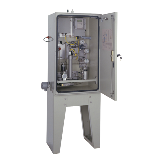
Section 2: System Installation Section 2: System Installation Standard System Components Standard primary components of the NJEX include the following: • System Enclosure, figure 1. Houses the pump, the Verometer, the odorant fill valve, the solenoid valve/ pneumatic relay manifold, the odorant discharge Expansion manifold, the system control enclosure. -
Page 16: System Flow Schematic
Section 2: System Installation System Flow Schematic Figure 4 Y Z S y s t e m s M i l t o n R o y • 2 0 1 I v y l a n d R o a d • I v y l a n d , P e n n s y l v a n i a • U S A • 1 8 9 7 4 • P : 2 8 1 . 3 6 2 . 6 5 0 0 • w w w. y z s y s t e m s . c o m Page 6 NJEX EUR ver. -
Page 17: Standard System Mounting
Section 2: System Installation Standard System Mounting Figure 5 2. In order to satisfy NEC requirements you 1. Bolt down the system enclosure to a concrete must connect a ground wire from the ground- slab using the mounting holes (9/16" (14.29mm)) ing lug located on the enclosure leg to a prop- provided in the bottom of each leg of the enclosure. -
Page 18: Standard System Connections
Section 2: System Installation Standard System Connections Required field connections to place the NJEX into operation are as follows: 1. Connect your I.S. Power Supply to the yellow cable connection coming from the bottom of the N-300 controller, and exiting the rear of your system enclosure, refer to the Wiring Control Document on page 117 in Appendix... - Page 19 Maximum tubing length should not exceed 4.5 meters with the tubing size maintained as indicated in this manual. If longer tubing lengths are required consult YZ Systems Technical Service Department at; 800.653.9435 or 281.362.6500. 3. Connect the odorant supply source to the odor- ant inlet mainfold with the recommended 6.35mm...
-
Page 20: Skid System Components
Section 2: System Installation The NJEX SkidMount Series of odorization systems is a total system approach to odorization. These sys- tems are completely factory assembled, tested, and delivered requiring only three field connections to be fully operational. The NJEX Skid Mount Systems offer all the advantages of our standard NJEX Systems plus the added benefit of an onboard odorant storage tank. - Page 21 Section 2: System Installation Actuation Gas Regulator • Bulk Odorant Filter, figure 9, provides primary odorant filtration between the storage tank and the NJEX. The bulk odorant filter is pre-installed inside the system enclosure attachment to the odorant source is via a bulk filter manifold equipped with 1/4”...
-
Page 22: System Flow Schematic
Section 2: System Installation System Flow Schematic Figure 11 Y Z S y s t e m s M i l t o n R o y • 2 0 1 I v y l a n d R o a d • I v y l a n d , P e n n s y l v a n i a • U S A • 1 8 9 7 4 • P : 2 8 1 . 3 6 2 . 6 5 0 0 • w w w. y z s y s t e m s . c o m Page 12 NJEX EUR ver. -
Page 23: Skid System Mounting
Section 2: System Installation Skid System Mounting Figure 12 3. Bolt the system to the concrete slab using 1. Prepare a concrete slab that exceeds the the 19.5mm mounting holes provided in the NJEX skid length and width dimensions by skid. - Page 24 Section 2: System Installation CONTAINMENT SKID SYSTEMS TANK CABINET WEIGHT Liters Simple 1422 1820 L + 304.8mm 19.05mm W - 203.2mm W + 304.8mm Y Z S y s t e m s M i l t o n R o y • 2 0 1 I v y l a n d R o a d • I v y l a n d , P e n n s y l v a n i a • U S A • 1 8 9 7 4 • P : 2 8 1 . 3 6 2 . 6 5 0 0 • w w w. y z s y s t e m s . c o m Page 14 NJEX EUR ver.
-
Page 25: Skid System Connections
Section 2: System Installation Skid System Connections Required field connections to place the NJEX into operation are as follows: 1. Connect your I.S. Power Supply to the yellow cable connection coming from the bottom of the N-300 controller, and exiting the rear of your sys- tem enclosure, refer to the Wiring Control Docu- ment on page 117 in Appendix D. - Page 26 Section 2: System Installation CAUTION: Excessive tubing lengths should be avoided. Installa- tion of the NJEX Odorization system should be as close to the point of injection and Odorant Storage Tank as possible. Maximum tubing length should not exceed 4.5 meters with the tubing size maintained as indicated in this manual.
-
Page 27: Section 3: Filling The Bulk Odorant Tank
Section 3: Filling the Bulk Odorant Tank Section 3: Filling the Bulk Odorant Tank Filling the Tank for the First 3. To purge the tank open valve V10 to introduce Time inert or natural gas to the tank to begin displacing any ambient air from the empty tank. -
Page 28: Refilling The Bulk Odorant Tank
Section 3: Filling the Bulk Odorant Tank Refilling the Bulk Odorant Tank 3. Connect a line from V11 to a flare or vapor recov- CAUTION: ery device, and open V11. Odorant has a very strong odor, which if allowed to escape to the atmosphere, may cause problems in 4. -
Page 29: Section 4: System Control & Electronics
Section 4: System Control & Electronics Section 4: System Control & Electronics Overview Individual components of the system are shown below and are described in the following pages. A flow chart of the N-300G controller menu system is illustrated on the N-300G Display Diagram located on page 116 in Appendix D:... -
Page 30: To Power Up The System
Section 4: System Control & Electronics To Power Up The System pmp bat vmtr sig tnk Open the N-300G Controller Enclosure, figure 19, and PropFlow Idle find the toggle switch S1 located just below center on *Stop *Dsp *Set the right side of the Printed Circuit Board – PCB. Turn on the main power switch by toggling the switch to up position. -
Page 31: Test & Standby Keys
Section 4: System Control & Electronics Test & Standby Keys The Test key, figure 26, is located in the upper right quadrant of the N-300G touch pad and is used to pmp bat vmtr sig tnk PropFlow 0:00 manually stroke the pump. Simply press the test key *Stop *Dsp *Set touch pad to stroke the pump. -
Page 32: Battery & Solar Panel Assembly
Section 4: System Control & Electronics ATEX System Connections Required field connections to place the NJEX into operation are as follows: 1. Connect your I.S. Power Supply to the yellow cable connection coming from the bottom of the N-300 controller, and exiting the rear of your system enclosure, refer to the Wiring Control Document on page 117 in Appendix... -
Page 33: Communications Interface
Section 4: System Control & Electronics Communications Interface There are three methods of communicating informa- tion out of the N-300 controller. • Method 1, utilizes Communications Modbus pro- tocol. Specifications to permit configuration can be found on page 108, Appendix B: N300 Modbus Specifications. - Page 34 Section 4: System Control & Electronics Notes Y Z S y s t e m s M i l t o n R o y • 2 0 1 I v y l a n d R o a d • I v y l a n d , P e n n s y l v a n i a • U S A • 1 8 9 7 4 • P : 2 8 1 . 3 6 2 . 6 5 0 0 • w w w. y z s y s t e m s . c o m Page 24 NJEX EUR ver.
-
Page 35: Section 5: Programming For Proportional-To-Flow Operation
Section 5: Programming for Proportional-to-Flow Operation Setting Operator Input Parameters designates optional key function • Choose Set in the main menu, figure 27. pmp bat vmtr sig tnk PropFlow Idle *Strt *Dsp *Set Figure 27 • Choose Par – parameters in the set selection menu, figure 28. -
Page 36: Max Gas Flow In M3/Sec
Section 5: Programming for Proportional-to-Flow Operation Setting Operator Input Parameters, Continued Max gas flow in m3/sec Max gas flow is the maximum flow rate at which the pmp bat vmtr sig tnk pmp bat vmtr sig tnk flow input reaches full scale span. Maximum Gas Flow Maximum Gas Flow 15.00... -
Page 37: Maximum Time/Stroke
Section 5: Programming for Proportional-to-Flow Operation To set the flow (no signal) input, figure 36a, press and release the Select key. The value entry will begin pmp bat vmtr sig tnk to flash when selected. Use the Up Arrow key to Flow (No Signal) increase the value and the Down Arrow key to de- 20.0% Max Gas Flow... -
Page 38: Odorant Tank
Section 5: Programming for Proportional-to-Flow Operation Setting Operator Input Parameters, Continued Odorant Tank Optional Set-up: Functional ONLY if a complete YZ Skid Mounted Tank System is supplied. 1. Disabled: no level monitoring, 0% = disabled, both Low & High settings must be disabled. pmp bat vmtr sig tnk Odorant Tank 2. -
Page 39: Odorant Inlet Pressure Monitoring
Section 5: Programming for Proportional-to-Flow Operation To set the alarm level points, figure 51, press and release the Select key. The Low Pressure value will begin to flash when chosen. Use the Up Arrow key to increase the value and the Down Arrow key pmp bat vmtr sig tnk pmp bat vmtr sig tnk Expansion Tanks (bar) -
Page 40: Alarm To Relay Delay
Section 5: Programming for Proportional-to-Flow Operation Setting Operator Input Parameters, Continued Alarm to Relay Delay pmp bat vmtr sig tnk Is a programmable time that can be entered to allow Maximum Time/Stroke pmp bat vmtr sig tnk for a period of time to occur between the initial issu- Alarm to Relay Delay 0 = Disabled 0 minutes... -
Page 41: Modbus Parameters
Section 5: Programming for Proportional-to-Flow Operation is programed this function will be disabled, figure 55. Conclusion This concludes programming the N-300G controller Note: the Modbus address is also used as the Sentry4 in Proportional-to-Flow Mode. If this NJEX System is I.D. - Page 42 Section 5: Programming for Proportional-to-Flow Operation Notes Y Z S y s t e m s M i l t o n R o y • 2 0 1 I v y l a n d R o a d • I v y l a n d , P e n n s y l v a n i a • U S A • 1 8 9 7 4 • P : 2 8 1 . 3 6 2 . 6 5 0 0 • w w w. y z s y s t e m s . c o m Page 32 NJEX EUR ver.
-
Page 43: Section 6: Programming For Proportional-To-Time Operation
Section 6: Programming for Proportional-to-Time Operation *designates optional key function Setting Operator Input Parameters pmp bat vmtr sig tnk PropFlow Idle Choose Set from the main menu, figure 57. *Strt *Dsp *Set Figure 57 Choose Par from the set selection menu, figure 58. pmp bat vmtr sig tnk Set Selection Choose Time from the set parameters menu,... -
Page 44: The Odorant Output Setting
Section 6: Programming for Proportional-to-Time Operation Setting Operator Input Parameters, Continued When a new value has been chosen, press the Enter key to store the new value into memory. The entered value will stop flashing when it has been loaded into memory. -
Page 45: Expansion Tank Pressure Monitoring
Section 6: Programming for Proportional-to-Time Operation it has been loaded into memory, the High Level value will begin to flash. Use the Up Arrow key to increase the value and the Down Arrow key to decrease the de- sired value. This alarm should typically be set at less than 80%. -
Page 46: Alarm To Relay Delay
Section 6: Programming for Proportional-to-Time Operation Setting Operator Input Parameters, Continued To set the alarm level points, figure 68, press and release the Select key. The Odorant Inlet Low value will begin to flash when chosen. Nominal low pressure pmp bat vmtr sig tnk pmp bat vmtr sig tnk in the Odorant Storage Tank is 2.07 Bar. -
Page 47: Modbus Address
Section 6: Programming for Proportional-to-Time Operation To set the alarm to call out delay time, figure 70, press and release the Select key. The Alarm to Callout Dly value will begin to flash when chosen. Use the Up Arrow key to increase the value and the Down Arrow key to decrease the value. -
Page 48: Conclusion
Section 6: Programming for Proportional-to-Time Operation Setting Operator Input Parameters, Continued MODBUS Parameters COMM = . . ONLY Communications Port #2 will be available for communications using Sentry Soft- ware Communications Protocol. COMM = 1 . Communications Port #1 will be available for Modbuss Communications, and Communica- tions Port #2 will be available for communications using Sentry Software Communications Protocol. -
Page 49: Section 7: Calibrating Signal Inputs
Section 7: Calibrating Signal Inputs Section 7: Calibrating Signal Inputs Analog Flow Input Calibration, 1-5 VDC / 4-20 mA pmp bat vmtr sig tnk PropFlow Idle IMPORTANT: *Strt *Dsp *Set Figure 73 Many factors effect the signal between the signal pmp bat vmtr sig tnk source and the NJEX System. - Page 50 Section 7: Calibrating Signal Inputs Analog Flow Input Calibration, 1-5 VDC / 4-20 mA, Continued To calibrate the zero set point, figure 81, apply 1.00 VDC (4.0 mA) to the TB1 terminal #2 (+ positive sig- nal input) and terminal #3 (- negative signal input). If a Differential Pressure Transducer –...
-
Page 51: Expansion Tank Pressure Transmitter Zero Calibration
Section 7: Calibrating Signal Inputs Expansion Tank Pressure Transmitter Zero Calibration Note: the N-300G should be in the stopped mode when performing the following calibrations. Choose *Set in the main menu, figure 88. pmp bat vmtr sig tnk Choose *Cal in the set selection menu, figure 89. PropFlow Idle *Strt... -
Page 52: Odorant Inlet Pressure Transmitter Zero Calibration
Section 7: Calibrating Signal Inputs Odorant Inlet Pressure Transmitter Zero Calibration Note: the N-300G should be in the stopped mode pmp bat vmtr sig tnk when performing the following calibrations. PropFlow Idle *Strt *Dsp *Set Figure 96 Choose *Set in the main menu, figure 96. Choose *Cal in the set selection menu, figure 97. - Page 53 Section 7: Calibrating Signal Inputs To calibrate the zero set point, The output from the transmitter should be 1.00 VDC. 1. Press & release the *Read key and the actual voltage present from the transmitter will be shown flashing in the display, figure 102. pmp bat vmtr sig tnk Zero Adjustment *Read...
-
Page 54: Pulse Flow Input Calibration, Dry Contact & Voltage Pulse
Section 7: Calibrating Signal Inputs Pulse Flow Input Calibration, Dry Contact & Voltage Pulse pmp bat vmtr sig tnk PropFlow Idle *Strt *Dsp *Set Figure 105 Choose *Set from the main menu, figure 105. Choose *Cal from the set select menu, figure 106. pmp bat vmtr sig tnk Set Selection *Par... -
Page 55: Calculation For Determining The Span Frequency Example
Section 7: Calibrating Signal Inputs Figure 113 Calculation for Determining the Span Frequency Pulse max flow rate CF = Pulses As determined by the flow metering device Example: 1 pulse 1,000,000CF 100,000 pulses/hr 10CF Since pulses per hour is not an option for programming the N-300G divide by 60 minutes per hour to obtain pulses per minute. - Page 56 Section 7: Calibrating Signal Inputs Notes Y Z S y s t e m s M i l t o n R o y • 2 0 1 I v y l a n d R o a d • I v y l a n d , P e n n s y l v a n i a • U S A • 1 8 9 7 4 • P : 2 8 1 . 3 6 2 . 6 5 0 0 • w w w. y z s y s t e m s . c o m Page 46 NJEX EUR ver.
-
Page 57: Section 8: Working With The N-300 System Displays
Section 8: Working with the N-300 System Displays Display Functionality Characters in the display will change to indicate the varying conditions of NJEX System operation. As discussed in Section 1: First Things to Know, Typo- and in graphic Conventions, page 1 Section 4: System the display inter- Control and Electronics, page 19... -
Page 58: To View Real Time Displays
Section 8: Working with the N-300 System Displays To View Real Time Displays pmp bat vmtr sig tnk Choose *Dsp in the main menu, figure 117. PropFlow Idle *Strt *Dsp *Set Figure 117 Strokes signaled are the number of pump strokes signaled by the N-300G controller are shown in this pmp bat vmtr sig tnk display, figure 118. -
Page 59: Meter Level - Verometer
Section 8: Working with the N-300 System Displays pmp bat vmtr sig tnk Meter Level – Verometer Meter Level 00.0% *Fill This display illustrates the Verometer level in percent. Figure 126 As odorant is pumped out of the Verometer, the N-300G controller will automatically refill the meter when the pmp bat vmtr sig tnk pmp bat vmtr sig tnk... -
Page 60: Expansion Tank
Section 8: Working with the N-300 System Displays To View Real-Time Displays, pmp bat vmtr sig tnk pmp bat vmtr sig tnk Expansion Tank Expansion Tank Continued 25.2 psig 1.739 bar Figure 129 Expansion Tank This display illustrates the expansion tank pressure, pmp bat vmtr sig tnk pmp bat vmtr sig tnk figure 129. -
Page 61: Tank Level
Section 8: Working with the N-300 System Displays Note: the flow input display is active in the Propor- tional-to-Flow mode only. pmp bat vmtr sig tnk Tank Level Tank Level This display, figure 139, illustrates the odorant supply Figure 139 level in the bulk odorant storage tank. - Page 62 Section 8: Working with the N-300 System Displays Notes Y Z S y s t e m s M i l t o n R o y • 2 0 1 I v y l a n d R o a d • I v y l a n d , P e n n s y l v a n i a • U S A • 1 8 9 7 4 • P : 2 8 1 . 3 6 2 . 6 5 0 0 • w w w. y z s y s t e m s . c o m Page 52 NJEX EUR ver.
-
Page 63: Section 9: Setting & Testing Alarms
Section 9: Setting & Testing Alarms Section 9: Setting & Testing Alarms Setting Alarm Out Status pmp bat vmtr sig tnk Alarm outputs can be configured to enable or disable PropFlow Idle which alarms deactivate the alarm output contact *Strt *Dsp *Set Figure 143... - Page 64 Section 9: Setting & Testing Alarms Setting Alarm Out Status Continued To set the Verometer alarm status, figure 150, press pmp bat vmtr sig tnk pmp bat vmtr sig tnk Verometer Alarm Verometer Alarm and release the Select key. The entered value will Enabled Disabled begin to flash when chosen.
-
Page 65: Testing Alarm Out Status
Section 9: Setting & Testing Alarms Testing Alarm Out Status pmp bat vmtr sig tnk PropFlow Idle *Strt *Dsp *Set Alarm outputs that have been enabled will deactivate Figure 153 the alarm output contact located on TB1, terminals #17 and #18, refer to the Wiring Control Document on pmp bat vmtr sig tnk page 117 in Appendix D:... - Page 66 Section 9: Setting & Testing Alarms Testing Alarm Out Status Continued To Simulate the pump alarm status, figures 160, Over Pump pmp bat vmtr sig tnk PMP bat vmtr sig tnk press and release the Select key. The pmp Alarm in- Pump Alarm Pump Alarm dicator in the upper left area of the N-300G display will...
- Page 67 Section 9: Setting & Testing Alarms Press the Enter key to return to the simulation selec- tion screen. The display will stop flashing. Press the OverFlow >125% pmp bat vmtr sig tnk PMP bat vmtr SIG tnk Down Arrow key to advance to the next simulation Signal Alarm Pump Alarm Simulate...
-
Page 68: Setting The Clock
Section 9: Setting & Testing Alarms Setting The Clock Date Stamps Module The internal clock in the N-300G should be maintained to reflect the current local time and date. When a sys- tem is first placed into service the clock should be set for local time and date. - Page 69 Section 9: Setting & Testing Alarms Arrow key to increase the value and the Down Arrow key to decrease the value. When a new Minute value has been chosen, press the Enter key to store the new setting into memory. This concludes the Clock Setting Section.
- Page 70 Section 9: Setting & Testing Alarms Notes Y Z S y s t e m s M i l t o n R o y • 2 0 1 I v y l a n d R o a d • I v y l a n d , P e n n s y l v a n i a • U S A • 1 8 9 7 4 • P : 2 8 1 . 3 6 2 . 6 5 0 0 • w w w. y z s y s t e m s . c o m Page 60 NJEX EUR ver.
-
Page 71: Section 10: Mechanical System
Section 10: Mechanical System Section 10: Mechanical System Actuation Gas Regulator Overview The NJEX mechanical system, figures 169, 170 and 171 are composed of the bulk odorant filter, fill valve, Verometer, pump, odorant discharge manifold, NJEX gas supply filter, solenoid manifold, pneumatic relay manifold, and the expansion tank. -
Page 72: Odorant Inlet Manifold & Bulk Odorant Filter Assembly
Section 10: Mechanical System Odorant Inlet Manifold & Bulk Odorant Filter Assembly The odorant inlet manifold & bulk odorant filter assem- bly, figure 172, is located adjacent to each pump / verometer assembly and performs the following func- tions: • Provides the system’s odorant supply connection by means of a 1/4”... -
Page 73: Verometer
Section 10: Mechanical System The threaded inlet connection to the fill valve allows access to the check valve wafer, return spring, and o-ring seal without disturbing the diaphragm and its seals. Verometer The purpose of the Verometer, figure 174, is to act as an odorant meter, verifying the amount of injected odorant. -
Page 74: Model Pump
Section 10: Mechanical System The Pump The NJEX pump, figure 175, is a pneumatically actu- ated, positive displacement, reciprocating plunger pump. The Pump is actuated with compressed air or pipeline gas at a pressure of 2.07 - 4.14 Bar, refer to Section 2, the System Flow Schematic, illustration 2. -
Page 75: Njex Gas Filter
Section 10: Mechanical System the enclosure from right to left, these ports are for the expansion tank drain, the pipeline connection, and the expansion tank pressure connection. Two valves located this manifold control the flow of the odorant blanket gas through the manifold. The valve located on the left, with the blue knob is the purge valve, refer to Section 12: System Maintenance,... -
Page 76: Solenoid Valve & Pneumatic Relay Manifold
Section 10: Mechanical System Solenoid Valve & Pneumatic Relay Manifold Two low power solenoid valves are mounted on this manifold, figure 178. The solenoid valve, SV2 located on the left, actuates the fill valve, while the other sole- noid valve, SV1 located on the right, pilots the pump pneumatic relay valve. -
Page 77: Section 11: System Operation
Section 11: System Operation Section 11: System Operation Setting System Pressures and Valves The overflow protector, figure 181, incorporates a low pressure relief in the cap assembly for the purpose of maintaining the maximum expansion tank pressure at Before attempting to start the system, check for 1.72 Bar. - Page 78 Section 11: System Operation Turn the main power switch, located inside the N- 300G enclosure, figure 182. To access the switch, pull pmp bat vmtr sig tnk Display Contrast Adj out and upward on the lever located on the right side of the N-300G enclosure.
-
Page 79: To Stop The System
Section 11: System Operation pump a minimum of 20 times. Additional strokes may be necessary if the pump displacement is restricted with a pump stroke spacer. pmp bat vmtr sig tnk A decrease in the Verometer Level should be ob- PropFlow Stop served. - Page 80 Section 11: System Operation Notes Y Z S y s t e m s M i l t o n R o y • 2 0 1 I v y l a n d R o a d • I v y l a n d , P e n n s y l v a n i a • U S A • 1 8 9 7 4 • P : 2 8 1 . 3 6 2 . 6 5 0 0 • w w w. y z s y s t e m s . c o m Page 70 NJEX EUR ver.
-
Page 81: Section 12: System Maintenance
Section 12: System Maintenance Section 12: System Maintenance Preventative Maintenance Recommended Spare Parts List Schedule Part # Description Recommended A preventative maintenance program serves to an- Quantity ticipate maintenance issues prior to waiting until the A4-0010 3-way solenoid valve system requires service. Like changing the oil & filters A3-0290 Pneumatic relay valve in an automobile, by choosing to service the various... -
Page 82: Overflow Protector Assembly Inspection
Section 12: System Maintenance Overflow Protector Assembly Inspection The overflow protector assembly should be inspected as follows on each NJEX System in operation, figure 194: 1. Isolate the protector by closing valve V6 located just below the overflow protector on the expansion tank. -
Page 83: Low Pressure Relief Adjustment
Section 12: System Maintenance Note: This should be inspected by the maintenance technician on a regular basis. Caution should always be used as odorant may escape if the expansion tank has been allowed to filled with odorant. Odorant fill of the expansion tank is not a normal or recommended operating condition. -
Page 84: Conducting A Forward Purge
Section 12: System Maintenance Conducting a forward, reverse, and expansion tank purge Figure 197 1. Stop system from main screen on controller 2. Close V6 3. Use the down arrow on the controller to the Meter level window 4. Open V4 and increase expansion tank pressure to 3.4-4 Bar. - Page 85 Section 12: System Maintenance Figure 197 Y Z S y s t e m s M i l t o n R o y • 2 0 1 I v y l a n d R o a d • I v y l a n d , P e n n s y l v a n i a • U S A • 1 8 9 7 4 • P : 2 8 1 . 3 6 2 . 6 5 0 0 • w w w. y z s y s t e m s . c o m NJEX EUR ver.
-
Page 86: Venting Pressure Gas
Section 12: System Maintenance Venting Pressure Gas Figure 198 Refer to the Venting Pressure Gas Operational Sche- matic figure 198, on page 77. CAUTION: Vented Gas will have STRONG odorant smell. 1. Connect a Flare, Odorant Filter / Scrubber to Expansion Tank Vent on the back of the cabinet (outlet of V5) 2. - Page 87 Section 12: System Maintenance Figure 198 Y Z S y s t e m s M i l t o n R o y • 2 0 1 I v y l a n d R o a d • I v y l a n d , P e n n s y l v a n i a • U S A • 1 8 9 7 4 • P : 2 8 1 . 3 6 2 . 6 5 0 0 • w w w. y z s y s t e m s . c o m NJEX EUR ver.
-
Page 88: Filling The Verometer
Section 12: System Maintenance Filling the Verometer Figure 199 Refer to the Filling the Verometer Operational Sche- matic figure 199, on page 79. 1. Close V2, V3, and V5 2. Open V4 until the expansion tank gauge reads 25 psi (1.72 Bar). Close V4. 3. - Page 89 Section 12: System Maintenance Figure 199 Y Z S y s t e m s M i l t o n R o y • 2 0 1 I v y l a n d R o a d • I v y l a n d , P e n n s y l v a n i a • U S A • 1 8 9 7 4 • P : 2 8 1 . 3 6 2 . 6 5 0 0 • w w w. y z s y s t e m s . c o m NJEX EUR ver.
-
Page 90: Priming & Starting The Njex System
Section 12: System Maintenance Priming & Starting the NJEX System Refer to the Priming and Starting the NJEX System Operational Schematic figure 200, on page 81. 1. Scroll down to the meter level screen 2. Open V3 3. Manually stroke the pump with test switch until Verometer level starts to drop (3-4%) 4. - Page 91 Section 12: System Maintenance Figure 200 Y Z S y s t e m s M i l t o n R o y • 2 0 1 I v y l a n d R o a d • I v y l a n d , P e n n s y l v a n i a • U S A • 1 8 9 7 4 • P : 2 8 1 . 3 6 2 . 6 5 0 0 • w w w. y z s y s t e m s . c o m NJEX EUR ver.
- Page 92 Section 12: System Maintenance Notes Y Z S y s t e m s M i l t o n R o y • 2 0 1 I v y l a n d R o a d • I v y l a n d , P e n n s y l v a n i a • U S A • 1 8 9 7 4 • P : 2 8 1 . 3 6 2 . 6 5 0 0 • w w w. y z s y s t e m s . c o m Page 82 NJEX EUR ver.
-
Page 93: Section 13: Njex System Troubleshooting
These alarms should only be active with skid mounted above. odorizer and tank assemblies furnished pre-assembled by YZ Systems, Inc. The set points for these alarms are SAFETY NOTES adjustable in the parameter section of the N-300 control- • Always use extreme care when performing mainte- ler. -
Page 94: Tank Level Alarm Troubleshooting Steps
3. If problem can not be resolved at this point con- (Shield). Repair any loose or broken wires. tact YZ Systems Technical Service. b. Inspect the level sensor at the tank for possible damage or moisture in the sensor head. Repair or replace as required if moisture is inside the sensor. -
Page 95: Signal Alarms
Section 13: NJEX System Troubleshooting Signal Alarm Signal Alarm & Non-Alarm Troubleshooting Steps • The Loss / Signal alarm will be active only in the Analog Proportional-To-Flow mode. It indicates 1. The Loss of Flow alarm will only be active with that the flow signal voltage has dropped below a Linear or Non-linear Analog signal. -
Page 96: Low Flow Non-Alarm Indicator Troubleshooting Steps
Section 13: NJEX System Troubleshooting Signal Alarm & Non-Alarm Verometer Alarms Troubleshooting Steps, Continued There are a variety of Veromter alarms monitored 3. Low flow indication is not an actual alarm, but by the N-300 Controller to ensure correct and safe an indication that the system is reading the flow operation of the NJEX System. -
Page 97: Verometer Non-Alarm Indicators
Section 13: NJEX System Troubleshooting 1. Inspect all cables for any external damage such as cuts or crimps in the external cable sleeve or • XTank High alarm indicates the pressure in the moisture inside the cable connector. expansion tank has exceeded the defined high pres- sure set point for the Expansion Tank. -
Page 98: Verometer Slow-Fill Alarm Troubleshooting Steps
Section 13: NJEX System Troubleshooting Verometer No-Fill Alarm Verometer Slow-Fill Alarm Troubleshooting Steps, Troubleshooting Steps Continued IMPORTANT NOTE: 5. Verify that the status switch be in the run position. Prior to troubleshooting a slow fill alarm, verify that the If no pneumatic supply is received at the fill valve Verometer is not in a full level position as the fill valve when a fill is called for, test electrical supply to the fill... -
Page 99: Verometer Fill Valve Failure Alarm Troubleshooting Steps
Section 13: NJEX System Troubleshooting 5. If the pipleine pressure is near or below 17.24 replace the fill valve. If the actuation gas is pres- Bar, a back pressure regulating device must be ent in the tube when disconnected, the Verometer installed immediately outside the NJEX enclosure, level should stabilize after disconnecting the fill on the odorant line leading to the pipeline injec-... -
Page 100: Verometer Odorant Inlet Low Alarm Troubleshooting Steps
Section 13: NJEX System Troubleshooting Verometer Odorant Inlet Low Verometer Expansion Tank Cable Alarm Troubleshooting Steps Alarm Troubleshooting Steps When an active OdorInlet Lo alarm is indicated the When an active XTank-Cable alarm is indicated the following steps should be taken: following steps should be taken: 1. -
Page 101: Verometer Expansion Tank High Alarm Troubleshooting Steps
Section 13: NJEX System Troubleshooting Verometer Expansion Tank the odorant storage tank and the NJEX System. High Alarm Troubleshooting Steps This should slow the fill rate. Repeate step 3 until the NJEX System fills in over 30 seconds, and the fill valve turns off between 100 - 108% of fill When an active XTank High alarm is indicated the volume. -
Page 102: Pump Over Pumping Alarm Troubleshooting Steps
Section 13: NJEX System Troubleshooting by the varying pressures and temperatures in IMPORTANT NOTE: the pipeline for pressures less than 17.24 Bar. If a back pressure regulating device is not in- When a system re-start is requested at completion or stalled as described above, install the device during the the service of an NJEX System, use the N-300 before proceeding. -
Page 103: Pump Failure Alarm Troubleshooting Steps
Section 13: NJEX System Troubleshooting tion. If not, remove the actuation cylinder. Inspect for ly set system operation. Inspect for valve settings a broken return spring, or a stuck / sticking actuator that can restrict pump displacement. piston or plunger. Replace the spring if broken. Clean 4. - Page 104 Section 13: NJEX System Troubleshooting noid is bad and should be replaced. the oil level reference mark inside of the oil reservoir about half way down with proper oil. e. If the above test indicates the solenoid is If the pump was completely out of oil, or if functioning, next determine if the signal is be- the level was below the top of the nipple, the ing sent by the controller, or lost in the cabling...
-
Page 105: Njex Model 7300 Pump Assembled
Appendix A: Appendix A: Illustrations Illustrations NJEX Model 7300 Pump Assembled, Figure 201 Actuation Gas Replacement Pump Seal Kit PN: D3-0131 Odorant Actuation Gas Hydrualic Oil Y Z S y s t e m s M i l t o n R o y • 2 0 1 I v y l a n d R o a d • I v y l a n d , P e n n s y l v a n i a • U S A • 1 8 9 7 4 • P : 2 8 1 . 3 6 2 . 6 5 0 0 • w w w. y z s y s t e m s . c o m NJEX EUR ver. -
Page 106: Njex Model 6300 Pump Assembled
Appendix A: Illustrations NJEX Model 7300 Pump Actuation Assembly, Exploded View, Figure 202 Stroke Spacers Part Volume Color Actuation Cylinder Number PN: B0-0078 100% B0-1061 Green B0-0103 Yellow B0-0104 Black B0-0062 Purple B0-0102 Silver B0-0101 Blue B0-0100 Gold B0-0063 Cartridge Nut PN: B0-0083 Piston Seal Plunger Seal... -
Page 107: Njex Model 7300 Pump Actuation Assembly, Exploded View
Appendix A: Illustrations NJEX Model 7300 Pump Diaphragm Cartridge, Exploded View, Figure 203 Pump Housing PN: B0-0069 O-Ring PN: A5-2115 O-Ring PN: A5-1121 PN: B0-0072 O-Ring PN: A5-2023 O-Ring PN: A5-1027 Diaphragm PN: A6-0087 Cartridge Piston PN: B0-0070 PN: B0-0071 Spring PN: C3-0002 O-ring... -
Page 108: Appendix A: Illustrations
Appendix A: Illustrations NJEX Model 7300 Pump Check Valve Assembly, Exploded View, Figure 204 O-ring PN: A5- 1115 Discharge Check Cartridge PN: B0-00756 1115A5-1129 Check Wafer PN: B0-0074 Sleeve O-Ring PN: A5-1012 PN: B0-0076 Check Wafer PN: B0-0074 O-Ring Seal Nut PN: A5-1016 PN: B0-0074 B0-0077... -
Page 109: Njex Model 7300 Pump, Diaphragm Cartridge, Exploded View
Appendix A: Illustrations 7300 Verometer, with Filter As- sembly Exploded View, Figure 205 Y Z S y s t e m s M i l t o n R o y • 2 0 1 I v y l a n d R o a d • I v y l a n d , P e n n s y l v a n i a • U S A • 1 8 9 7 4 • P : 2 8 1 . 3 6 2 . 6 5 0 0 • w w w. y z s y s t e m s . c o m NJEX EUR ver. -
Page 110: Njex Model 7300 Pump, Check Valve Assembly, Exploded View
Appendix A: Illustrations NJEX Model 6300 Pump Assembled, Figure 206 Y Z S y s t e m s M i l t o n R o y • 2 0 1 I v y l a n d R o a d • I v y l a n d , P e n n s y l v a n i a • U S A • 1 8 9 7 4 • P : 2 8 1 . 3 6 2 . 6 5 0 0 • w w w. y z s y s t e m s . c o m Page 100 NJEX EUR ver. -
Page 111: Njex Model 6300 Pump, Check Valve Assembly, Exploded View
Appendix A: Illustrations NJEX Model 6300 Pump Actuation Assembly, Exploded View, Figure 207 Y Z S y s t e m s M i l t o n R o y • 2 0 1 I v y l a n d R o a d • I v y l a n d , P e n n s y l v a n i a • U S A • 1 8 9 7 4 • P : 2 8 1 . 3 6 2 . 6 5 0 0 • w w w. y z s y s t e m s . c o m NJEX EUR ver. -
Page 112: Fill Valve, Exploded View
Appendix A: Illustrations NJEX Model 6300 Pump Check Valve Assembly, Exploded View, Figure 208 Y Z S y s t e m s M i l t o n R o y • 2 0 1 I v y l a n d R o a d • I v y l a n d , P e n n s y l v a n i a • U S A • 1 8 9 7 4 • P : 2 8 1 . 3 6 2 . 6 5 0 0 • w w w. y z s y s t e m s . c o m Page 102 NJEX EUR ver. -
Page 113: 7300 Verometer, With Filter Assembly, Exploded View
Appendix A: Illustrations 6300 Verometer, with Filter Assembly Exploded View, Figure 209 B3-0214 V-020 Y Z S y s t e m s M i l t o n R o y • 2 0 1 I v y l a n d R o a d • I v y l a n d , P e n n s y l v a n i a • U S A • 1 8 9 7 4 • P : 2 8 1 . 3 6 2 . 6 5 0 0 • w w w. y z s y s t e m s . c o m NJEX EUR ver. - Page 114 Appendix A: Illustrations Fill Valve, Exploded View, Figure 210 SS Bolts, 4 each Tubbing Fitting PN: C0-0215 PN: A1-0012 Upper Housing PN: A3-0205 Diaphragm O-Ring PN: A6-0087 PN: A5-1027 O-Ring PN: A5-1030 O-Ring PN: A5-1023 Dart PN: A3-0206 Lower Housing PN: A3-0207 O-Ring PN: A5-1012...
-
Page 115: Bulk Odorant Filter
Appendix A: Illustrations Bulk Odorant Filter Figure 211 *O-Ring P.N A5-1334 Y Z S y s t e m s M i l t o n R o y • 2 0 1 I v y l a n d R o a d • I v y l a n d , P e n n s y l v a n i a • U S A • 1 8 9 7 4 • P : 2 8 1 . 3 6 2 . 6 5 0 0 • w w w. y z s y s t e m s . c o m NJEX EUR ver. -
Page 116: Njex Gas Filter
Appendix A: Illustrations NJEX Gas Filter Figure 212 Gas Filter Label Gas Filter Cap PN: D5-0074 PN: C4-0130 O-Ring 334 Viton PN: A5-1334 Filter Suspension PN: C4-0109 Coalescing Filter Element PN: C4-0133 Filter Locator Bushing PN: C4-0132 Filter Retainer Washer PN: C4-0102 1/4”... -
Page 117: Electronics Assembly
Appendix A: Illustrations Electronics Assembly Figure 213 Y Z S y s t e m s M i l t o n R o y • 2 0 1 I v y l a n d R o a d • I v y l a n d , P e n n s y l v a n i a • U S A • 1 8 9 7 4 • P : 2 8 1 . 3 6 2 . 6 5 0 0 • w w w. y z s y s t e m s . c o m NJEX EUR ver. -
Page 118: Appendix B: N-300 Modbus Specifications
Appendix B: Appendix B: N-300 Modbus Specifications N-300 Modbus Specifications Communications Settings Protocol ................Modbus Data framing ..............Modbus RTU and ASCII Slave Address range ............0-247, 0 = Modbus disabled Baud rates ................. 1200, 2400, 4800, and 9600 Number of data bits ............7 or 8 Parity ................. -
Page 119: Status Functions
Appendix B: N-300 Modbus Specifications Boolean Registers Control Functions, Continued Address Access Description 00007.... Read/Write ....Local/Remote Load Cycle Control (toggle) (Liquid System Only) 00008.... Read/Write ....Proportional to Time/Flow mode (toggle) 00009.... Read/Write ....Save Parameters to EEPROM 00010.... Read/Write ....Remote Inhibit / Run the N-300 (toggle) 00011 .... -
Page 120: Alarm Functions
Appendix B: N-300 Modbus Specifications 00119 .... Read Only ....Normal (0) / Remote Inhibit (1) 00120.... Read Only (L) ..New HOU/FLOW Data Available 00121.... Read Only ....No Load Cycle (0) / Load Cycle Active (1) – Liquid System Only Alarm Functions The alarm functions available via Modbus are listed below. -
Page 121: Integer Registers
Appendix B: N-300 Modbus Specifications Integer Registers The integer data type could be used for the Results data and configuration/control parameters. The “holding registers” as referred to by the Modbus specification, are read/write registers. This 16-bit integer data type can be manipulated using functions 3, 6, and 16. -
Page 122: Parameter Functions
Appendix B: N-300 Modbus Specifications * Model Specific Formatting information for Result Data functions Address Description 40001...... High bytes for Accumulated odorant injected, combine with address 40002 for total. 40002...... 6300GE/LE = .XXXXX, 7300GE/LE = X.XXXX, 8300GE/LE = XX.XXX (lbs), 6300GM/LM = .XXXXX, 7300GM/LM = X.XXXX, 8300GM/LM = XX.XXX (kg) Note: Low bytes only, combine with address 40001 for total odorant injected. -
Page 123: Exception Responses
Appendix B: N-300 Modbus Specifications Parameter functions, Continued 40116 .... Read/Write ....Odorant Tank Level High (xx %) – Unsigned Integer 40117 .... Read/Write ....Odorant Tank Level Low (xx %) – Unsigned Integer 40118 .... Read/Write ....Expansion Tank Pressure High (xx.x psi / x.xxx bar) – Unsigned Integer 40119 .... -
Page 124: Appendix C: Response Forms
Appendix C: Response Forms For the Record Parameters To assit in trouble shooting, if required, please record the following information as the NJEX is intitalized for • Injection Rate: _____________________________ the first time. • Pump Displacement: ________________________ • Odorant Density: ___________________________ Basic information on the NJEX •... -
Page 125: Njex Trouble Shooting Form
NJEX TROUBLE SHOOTING FORM ReturnTo: F: 281.362.6500, Em: techsupport@yzhq.com NJEX Model Number: NJEX (serial number/N-300G version x.xx/mfg. date): Date: Your Name: LOCATION: Site ID: Attending Technicicans: Telephone: CONDITIONS: Pipeline Pressure: Expansion Tank 1.72 Bar: Bulk Tank 2.07-2.41 Bar: cc/stroke: Supply Actuation 5.17 Bar: Pump Actuation (See Flow Chart for pressure): meter level: Gas Flow Rate m3/sec.:... -
Page 126: Appendix D: Documents
Appendix D: Documents Serial Number xxxxx N-300 Controller Display Model Type 7300G Diagram, Figure 214 Verometer Calibrate xx.xxx calicrate cc Pre-Config N-300G Ver x.xx -- NJEX -- pmp bat vmtr sig tnk PropFlow (Time) Idle *Strt *Dsp *Set pmp bat vmtr sig tnk Set Selection *Par *Cal... -
Page 127: Wiring Control Document
Appendix D: Documents Wiring Control Document, 1E-0345.dwg () Figure 215 2 of 3 S y s t e m s M i l t o n R o y • 2 0 1 I v y l a n d R o a d •... - Page 128 MILTON ROY LLC MILTON ROY EUROPE SAS 201 Ivyland Road 10, Grand Rue Ivyland, PA 18974, USA 27360 Pont Saint Pierre, France T: 800.344.5399 P: 281.362.6500 F: 281.362.6513 Sales@yzhq.com www.yzsystems.com...
Need help?
Do you have a question about the NJEX 6300G and is the answer not in the manual?
Questions and answers