Lumens VC-A61P User Manual
Hide thumbs
Also See for VC-A61P:
- User manual (52 pages) ,
- Firmware upgrade instructions (4 pages) ,
- Quick installation manual (2 pages)
Table of Contents

Related Manuals for Lumens VC-A61P


Summary of Contents for Lumens VC-A61P
- Page 1 VC-A61P / VC-A61PN HD camera (PTZ Video Camera) User Manual - English [Important] To download the latest version of Quick Start Guide, multilingual user manual, software, or driver, etc., please visit Lumens https://www.MyLumens.com/support...
-
Page 2: Table Of Contents
Table of Contents Copyright Information ..................2 Chapter 1 Safety Instructions ................. 3 Chapter 2 Package Contents ................4 Chapter 3 Function Introduction ..............5 3.1 I/O functions Introduction ..................5 3.2 Description of LED indicator ................7 3.3 Tally Indicator Light Function Description ............7 Chapter 4 Instruction for installation ............. -
Page 3: Copyright Information
Lumens Digital Optics Inc. unless copying this file is for the purpose of backup after purchasing this product. In order to keep improving the product, Lumens Digital Optics Inc. hereby reserves the right to make changes to product specifications without prior notice. The information in this file is subject to change without prior notice. -
Page 4: Chapter 1 Safety Instructions
Chapter 1 Safety Instructions Always follow these safety instructions when using the product: 1 Operation Please use the product in the recommended operating environment, away from water or source of heat. Do not place the product in tilted position or unstable trolley, stand or table. Please clean the dust on the power plug prior to usage. -
Page 5: Chapter 2 Package Contents
Chapter 2 Package Contents Instruction for VC-A61P / VC-A61PN Remote Control installation Quick Installation Guide Power Cord Power Adapter RS-422 Connector Appearance may vary depending on country/region Metal Plate A Metal Plate B M3 Screws Silver x8 / Black x2... -
Page 6: Chapter 3 Function Introduction
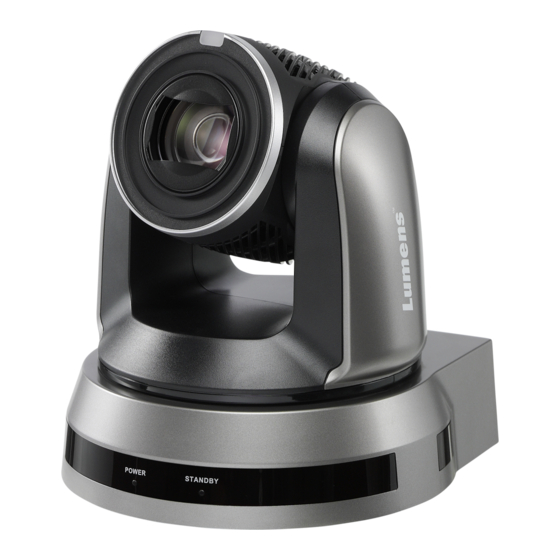
Chapter 3 Function Introduction 3.1 I/O functions Introduction 3.1.1 Front View Item Function Descriptions Tally indicator light Display the tally light status of the camera Camera lens 30x HD camera lens Power LED Display the status of the camera indicator Standby LED Display the status of the camera indicator... - Page 7 3.1.2 Back View Item Function Descriptions RS-232 input port, at most 7 cameras can be connected in a serial RS-232 input connection RS-232 output port, at most 7 cameras can be connected in a RS-232 output serial connection Kensington lock Lock hole of safety lock hole The remote control ID setting is only controlled after corresponding...
-
Page 8: Description Of Led Indicator
3.1.3 Bottom Item Function Descriptions Tripod lock hole The camera is mounted on a (specification) 1/4” - 20 UNC tripod 3.2 Description of LED indicator Status Power Standby Startup in progress Green light Orange light (initialization) In use Green light No indicator In standby mode No indicator... -
Page 9: Chapter 4 Instruction For Installation
Chapter 4 Instruction for installation 4.1 Preparation before installation Installation and connection of the HD camera requires special skills. To install by yourself, please follow necessary steps, ensure steady and tight installation of the device, and pay attention to your safety to avoid any accident. 4.1.1 Ensure the safety of the installation environment. - Page 10 4.2.2 I would like to install the camera on the ceiling 4.2.2.1 Prepare for the parts and equipment required during the installation 1. Accessories in the box (metal plates A, B, M3 screw silver x 8, black x 2) 2. Screw for locking on ceiling mounted hanger x 4 3.
- Page 11 4.2.2.4 Size Diagram 1. Bottom of machine The camera can be mounted on a 1/4”, -20 UNC PTZ tripod deck by using the lock holes on the bottom for the tripod English - 10...
- Page 12 Metal Plate size diagram Metal plate A - machine side Metal plate A locking screw Metal plate A - machine side English - 11...
- Page 13 Metal plate B - ceiling side Metal plate B locking bolt Metal plate B locking screw M3 threaded hole M3 threaded hole M3 threaded hole Metal plate B - ceiling side English - 12...
- Page 14 4.2.2.5 Precautions for installation 1. Before installation, please confirm the orientation of the machine relative to the object to be captured 2. It is recommended that the machine should be set at a distance of more than 1.5 meter away from the object to be captured. Please adjust for a best distance according to the magnification of the lens Projector 1.5 meter ↑...
-
Page 15: Connecting Devices
(2) Please reserve the hole for the connecting wires of the camera 4. Combine the metal plate A and the metal plate B (1) Push the metal plate A up to the ceiling and then to the right to latch the metal plate B (2) And then secure with 2 M3 silver screws and 1 M3 black screw black... - Page 16 <Remark> SDI supports the audio output of 48 KHz / resolutions up to 1080p 59.94/50 HDMI Cable SDI Cable 4.3.2 Connecting to an HDTV/computer monitor (HDMI) HDMI cable English - 15...
- Page 17 4.3.3 Connecting to Internet For details of web page connection setting and description, please refer to Chapter 6 Network Function Settings Description Network cable Router or Hub 4.3.4 Connecting AUDIO IN Set the [Audio In] in the OSD to reflect the input device Audio Cable MIC or audio mixer English - 16...
- Page 18 4.3.5 Connecting RS-232 With RS-232 in/out, at most 7 Lumens cameras can be connected. RS-232 pins definition instructions English - 17...
- Page 19 4.3.6 Connecting RS-422 With RS-422, at most 7 Lumens cameras can be connected. <Caution> When RS-422 connection is being used, do not use RS-232 connection. RS-422 pins definition instructions English - 18...
- Page 20 RS-422 connection instructions 1. Hold the two sides of RS-422 connector and pull out in the direction shown by the arrow in the figure below 2. Peel off a section of copper wire (AWG Nos. 28 to 18) and insert it into the connector hole;...
-
Page 21: Chapter 5 Remote Control And Setting Menu
Chapter 5 Remote Control and Setting Menu 5.1 Functions of remote control <Remark> The below functions are listed alphabetically. Item Description ,,, Move the lens Back Light Turn on/off back light compensation Camera select Choose Camera ID 1 ~ 3 Focus- Turn on manual focus to adjust the focal Manual /... -
Page 22: Setting Menu
5.2 Setting Menu <Remark> Press [Menu] on the remote control to enter the setting menu; the bold underlined values in the following table are defaults. 1st Level 2nd Level 3rd Level Function Descriptions Major Items Minor Items Adjustment Values 1. Full Auto 2. - Page 23 1st Level 2nd Level 3rd Level Function Descriptions Major Items Minor Items Adjustment Values 1. F1.6 2. F2 3. F2.2 4. F2.7 5. F3.2 6. F3.8 7. F4.5 8. F5.4 Adjustable when the Exposure Iris Pri 9. F6.3 mode is set to Iris Pri 10.
- Page 24 1st Level 2nd Level 3rd Level Function Descriptions Major Items Minor Items Adjustment Values 1/5000 1/5000 1/3000 1/3000 1/2500 1/2500 1/2000 1/1750 1/1500 1/1250 1/1000 1/1000 1/725 1/600 1/500 1/425 1/350 1/300 1/250 1/215 1/180 1/150 1/120 1/120 1/100 1/100 1/90 1/75 1/60...
- Page 25 1st Level 2nd Level 3rd Level Function Descriptions Major Items Minor Items Adjustment Values 1. 9 dB 2. 12 dB 3. 15 dB 4. 18 dB 5. 21 dB 6. 24 dB Gain Limit 7. 27 dB Max. limit value of electron gain 8.
- Page 26 1st Level 2nd Level 3rd Level Function Descriptions Major Items Minor Items Adjustment Values Adjustable when the white balance Manual Blue 0 ~ C ~ 128 mode is set to Manual 1. Off Picture effect 2. Neg 3. B & W Sharpness 0 ~ A ~ 14 1.
- Page 27 1st Level 2nd Level 3rd Level Function Descriptions Major Items Minor Items Adjustment Values Tilt UP Limit 0 ~ 90 Limit the upward angle Tilt Down Limit -30 ~ 0 Limit the downward angle Pan Flip On / Off Activate the reverse Pan command Tilt Flip On / Off Activate the reverse Tilt command...
- Page 28 1st Level 2nd Level 3rd Level Function Descriptions Major Items Minor Items Adjustment Values Press [ENTER] to be in modify mode; select the item to be modified using the up and down IP Address 192.168.100.100 keys, and modify the value using the left and right keys or the numeric keys.
- Page 29 1st Level 2nd Level 3rd Level Function Descriptions Major Items Minor Items Adjustment Values Set the encode type and sample rate 48 KHz(AAC) 44.1 KHz(AAC) <Remark> SDI supports the audio Encode output of 48 KHz only 16 KHz(AAC) Sample Rate 16 KHz(G.711) <Remark>...
- Page 30 1st Level 2nd Level 3rd Level Function Descriptions Major Items Minor Items Adjustment Values 1. 3840 x 2160/29.97p 2. 3840 x 2160/25p 3. 1080p/59.94 Choose the output resolution 4. 1080p/50 <Remark>VC-A61PN does not Output Mode 5. 1080p/29.97 support 720p/29.97 and 720p/25 6.
-
Page 31: Chapter 6 Network Function Settings Description
Chapter 6 Network Function Settings Description 6.1 Connecting Camera to Network 6.1.1 Connecting to Internet Two common connection methods are shown below 1. Connecting via switch or router Network cable Network cable Switch or router Camera Computer 2. To connect directly through network cable, the IP address of the computer should be changed so that it is on the same network segment as the camera e.g.: The factory-preset default IP address of the camera is 192.168.100.100. - Page 32 Password: 9999 6.1.3 Using Lumens VMS Software to View the Images <Remark> Lumens VMS is for VC-A61P only and cannot work with VC-A61PN Open LUMENS VMS software (Please download from the Lumens official website) Search for the camera: Press...
- Page 33 6.1.4 Using RTSP Player to View the Images <Remark> This is only applicable to VC-A61P. VC-A61PN does not support RTSP Streaming In addition to the browser and VMS, other free softwares also can be used for RTSP connection,such as VLC, Quick Time and PotPlayer RTSP connection address formats are as follows: ...
-
Page 34: Web Page Function Description
6.2 Web Page Function Description 6.2.1 Login Screen Item Function Descriptions Username Enter user account (default: admin) Enter user password (default: 9999) Password When log in for the first time, please refer to 6.2.3 Account Management to change the default password. Currently, the system supports English, Traditional Chinese and Language selection Simplified Chinese... - Page 35 6.2.2 Viewing In Real Time Item Function Descriptions Pan / Tilt setting Adjust the Pan/Tilt position of the camera screen Zoom ratio Adjust the zoom-in or zoom-out ratio via scroll bar Display the screen currently captured by the camera Preview window <Remark>...
- Page 36 6.2.3 Account Management Item Function Descriptions Add user account Enter a user name and password to add a new user Set the new account management permissions User Type Admin Operator Viewer View images Permission setting Settings Account management Applying setting Add the newly created user to the list of account Edit: Modify the user password and permissions List of accounts...
- Page 37 6.2.4 Setting-System Setting <Remark> The figure is an example of VC-A61P. VC-A61PN does not support Preview Window Item Function Descriptions Set the resolution of the camera, resolutions supported by the camera are as follows: 3840 x 2160 29.97/25 fps 1080P 59.94/50/29.97/25 fps Resolution 720P 59.94/50/29.97/25 fps...
- Page 38 6.2.5 Setting - Video <Remark> Streaming related settings are only applicable to VC-A61P. VC-A61PN does not support this feature Item Function Descriptions Modify the camera name Camera names are limited to 1 - 12 characters Camera name Please use a camera name by mixing uppercase and lowercase letters or numbers.
- Page 39 6.2.6 Setting - Camera Item Function Descriptions Zoom ratio Adjust the zoom-in or zoom-out ratio via scroll bar Mode: Select exposure mode (Automatic/Shutter Priority/Aperture Priority/Manual) Exposure Comp. Level: Select exposure compensation level Gain: The gain limit is adjustable when the exposure mode is set to “Manual”...
- Page 40 Mode: Select manual/automatic focus Focus Range: The focusing range is adjustable when the focus mode is set to “Manual” Focus AF Sensitivity: Set automatic focus sensitivity AF Frame: Set automatic focus range Mirror Mirror: Set automatic flip mode D-Zoom Limit Set limits for digital zoom Setting - Picture...
- Page 41 6.2.8 Setting - Audio Item Function Descriptions Open audio Turn on/off sound Soundtrack effect Set MIC In/Line In setting Volume Adjust Volume On / Off audio signal delay Audio delay <Remark> VC-A61PN does not support this setting Set the audio signal delay time (-1~-500ms) Audio delay time <Remark>...
- Page 42 6.2.9 Setting - Network <Remark> Some settings are only applicable to VC-A61P. Please see the function descriptions below for details Item Function Descriptions Network setting of camera. Change of setting is available when DHCP Network function is closed. Copy the RTMP web address provided by the RTMP service platform...
- Page 43 <Remark> SNTP server address: Please change in network setting 6.2.11 Setting - Maintenance - Upgrading Firmware Item Function Descriptions The camera firmware may be upgraded via web page. For the upgrade Firmware Update method, please download the FW upgrade manual from Lumens official website English - 42...
- Page 44 6.2.12 Setting - Maintenance - Incident Log Item Function Descriptions If the camera encounters errors, an error code log will be established Event Logs <Remark> When an error code appears, please try to clear it to make sure whether the issue has occurred repetitively 6.2.13 Setting - Maintenance - System Service Item...
- Page 45 About 6.2.14 Item Function Descriptions Camera name Display the camera name Firmware Version Display the firmware version of the camera Serial No. Display the camera serial No. English - 44...
-
Page 46: Chapter 7 Dip Switch Setting
Chapter 7 DIP Switch Setting 7.1 DIP SWITCH 7.1.1 OUTPUT Switch To switch via the OSD/ RS-232 Command is also available based on the last executed action Resolution Frame Rate Remark 29.97 3840 x 2160p 59.94 1920 x 1080p 29.97 59.94 1280 x 720p <Remark>... -
Page 47: Chapter 8 Troubleshooting
Chapter 8 Troubleshooting This chapter describes problems you may encounter while using VC-A61P/VC-A61PN. If you have questions, please refer to related chapters and follow all the suggested solutions. If the problem still occurred, please contact your distributor or the service center. -
Page 48: Supplier's Declaration Of Conformity 47 Cfr § 2.1077 Compliance Information
Supplier's Declaration of Conformity 47 CFR § 2.1077 Compliance Information Manufacturer:Lumens Digital Optics Inc. Product Name:VC-A61P/ VC-A61PN Model Number:4KPTZ Video Camera Responsible Party – U.S. Contact Information Supplier:Lumens Integration, Inc. 4116 Clipper Court, Fremont, CA 94538, United States e-mail :support@mylumens.com FCC Compliance Statement This device complies with Part 15 of the FCC Rules.
Need help?
Do you have a question about the VC-A61P and is the answer not in the manual?
Questions and answers