Advertisement
Quick Links
INSTRUCTIONS POUR L' INST LL TION
INST LL TION
L'appareil ne nécessite pas de soins particuliers pour son installation mécanique et électrique.
Das Gerät benötigt keine speziellen elektrischen oder mechanischen Installationsvorberei-
vant de procéder à l'installation, il faut vérifier que les données indiquées sur la plaque
tungen. Bevor das Gerät eingebaut wird, muss das Typenschild mit den tatsächlichen
(tension, courant, fréquence) correspondent à celles du secteur.
Netzgegebenheiten (Spannung, Strom, Frequenz) verglichen wird.
PROGR MM TION
PROGR MMIERUNG
L'accès au menu de programmation est protégé par une clé logicielle constituée d'une com-
Die Änderung von Parameter in der Konfiguration ist nur nach richtiger Eingabe des
binaison numérique de 4 chiffres. Lors de la demande d'accès à la programmation, l'appareil
Zugangscodes (4-stellige Zahl) möglich. Damit in die Programmierung eingetreten werden
demande à l'opérateur de saisir au clavier la combinaison d'accès, en permettant ou en inter-
kann, verlangt das Gerät die Eingabe der Zutrittskombination. Je nach den eingeladenen
disant la possibilité de modifications des paramètres, selon le code chargé.
Code erlaubt oder sperrt des Gerät jegliche Parameteränderung.
La programmation est divisée sur deux niveaux (avec différentes clés d'accès).
Die Programmierung ist auf zwei Stufen (mit verschiedenen Zugriffsschlüssel) aufgeteilt.
NIVE U 1
STUFE 1
Mot de pas 1000
= type de connexion, type de puissance moyenne, temps de moyenne,
Kennwort 1000
= nschlusstyp, mittlerer Leistungstyp, mittlere Zeit, nzeigekontrast,
contraste du afficheur, communication RS485 ou sortie à impulsions Remise à zéro du:
Kommunikation RS485 oder Impulsausgang. Nullstellung von: mittlere Stromspitze,
pic de courant moyen, pic de puissance moyenne, compteur horaire, énergie partielle
1 2
mittlere Leistungsspitze, Betriebsstundenzähler, Teilenergie
NIVE U 2
STUFE 2
Mot de pas 2001
= rapport de transformation du transformateur de courant et de
Kennwort 2001
= externe Strom- und Spannungswandlerübersetzung
tension externes
Für Programmierung werden die 3 Tasten auf dem Frontteil benutzt:
Pour la programmation, utilisez les 3 touches sur l'avant :
DOWN + ENTER Programmierungseingang
DOWN + ENTER pour entrer dans le menu programmation
ENTER Datenbestätigung
ENTER confirmation des données
DOWN Cursorverschiebung
DOWN pour déplacer le curseur
UP Erhöhung des geladenen Wertes
UP augmente la valeur réglée. En cas de programmation, DOWN + ENTER pour sortir de la
Während der Programmierung, DOWN + ENTER Programmierungsausgang (ohne Änderun-
programmation (sans sauver les modifications).
genspeicherung).
Dans les cas où la programmation est chargeable à pas fixes (ex. type de connexion, remise à
Wenn die Programmierung bei festen Schritten geladen werden kann (z.B. nschlusstyp,
zéro des valeurs, etc.), les touches DOWN et UP permettent de sélectionner les valeurs dispo-
Wertenullstellung, und so weiter) gestatten DOWN und UP Tasten die verfügbare Werte
nibles.
auszuwählen.
Il est impossible d'accéder directement au niveau 2 de programmation avant d'avoir terminé
Es ist nicht möglich direkt zum Unterpunkt LEVEL 2 zu springen.
le niveau 1.
Die Programmierung beginnt immer mit LEVEL 1.
P R METRES PROGR MM BLES
PROGR MMIERB RE P R METER
• MOT DE P SSE 1000
• KENNWORT 1000
CONNEXION
NSCHLUSSTYP
L'appareil peut être utilisé pour connexion sur une ligne monophasée ou triphasée
(3 ou 4 fils).
Das Gerät kann für Einphasen- oder Drehstromleitungsanschluss (3 oder 4 Leitungen)
Choisir le type de connexion désiré et, lors du câblage, respecter scrupuleusement le schéma
benutzt werden. Wählen Sie die gewünschte nschlussart und erinnern Sie sich an dass, der
de saisie; une connexion erronée est source inévitable de fausses mesures ou de dommages à
nschluss gem. nschlussbilder erfolgt. Falschanschluss führt zu erheblichen nzeigefehlern!
l'appareil.
Es können sogar Beschädigungen auftreten.
La configuration d'entrée doit être complétée avec la programmation par clavier du type de
Die Eingangskonfiguration muss mit den Tastaturprogrammierung der ausgewählten
connexion désiré et des éventuels rapports de transformateurs de courant et de tension exté-
nschlusstyp und der eventuellen externen Strom- und Spannungswandlerverhältnisse
rieurs.
ergänzt werden. Verwirklichbare nschlusse:
Connexions réalisables :
1n1E
Schaltbild
S1000/220
Einphasenleitung
1n1E
S1000/220
ligne monophasée
3-2E
S1000/213
Drehstromleitung, 3 Leitungen, 2 ronsysteme
schéma
Schaltbild
3-2E
S1000/213
ligne triphasée, 3 fils, 2 Systèmes ron
3-3E
S1000/282
Drehstromleitung, 3 Leitungen, 3 Systeme
schéma
Schaltbild
3n3E
S1000/212
Drehstromleitung, 4 Leitungen
3-3E
schéma
S1000/282
ligne triphasée, 3 fils, 3 Systèmes
Schaltbild
CHTUNG! Bitte kontrollieren, dass das benutzte Schaltbild mit der Tastaturpro-grammie-
3n3E
schéma
S1000/212
ligne triphasée, 4 fils
TTENTION! Vérifier que le schéma de raccordement utilisé correspond à la configuration
rung der Konfiguration übereinstimmt.
effectuée par le clavier.
PRÜFUNG DER PH SENFOLGE
VERIFIC TION DE L SEQUENCE DE PH SES
Drücken NT R-Taste (in beliebigen nzeigeseite) wird geprüft, ob die Voltmeterphasen
La touche NT R (dans n'importe quelle page d'affichage) on fait le contrôle du correct
(Phasenfolge) richtig angeschlossen sind.
branchement des voltmétriques (séquence de phases)
Ob der nschluss korrekt ist, bleibt die nzeige unverändert.
Si le branchement est correct, l'affichage ne change pas.
Ob der nschluss falsch ist, wird rr 123 angezeigt. In diesem Fall müssen Sie den
Si le branchement est faux, rr 123 est affiché. Dans ce cas, il faut modifier le branche-
Voltmeterphasenanschluss berichtigen und die Prüfung wiederholen, bis Sie die richtige
ment des voltmétriques et refaire la vérification jusqu'à obtenir la séquence correcte.
Folge erreichen.
TTENTION! Une fausse séquence des phases est cause de erreurs dans la mesure
CHTUNG! Eine falsche Phasenfolge kann Messfehler verursachen.
ENERGIE
ENERGIE
Remise à zéro: énergie active partielle
Nullstellung: Teilwirkenergie
PUISS NCE MOYENNE / COUR NT MOYENNE
MITTLERE LEISTUNG / MITTLERE STROM
Integrationszeit: 5, 8, 10, 15, 20, 30, 60 minutei
Temps d'intégration: 1, 8, 10, 15, 20, 30, 60 minutes
Verbundene Leistung: Wirk- Blind- oder Scheinleistung
Puissance associée: active, réactive, apparente
Remise à zéro: valeur maximale de la puissance moyenne et de la courant moyenne
Nullstellung: Höchstwert der mittleren Leistung und mittlere Strom
COMPTEUR HOR IRE
BETRIEBSSTUNDENZÄHLER
Nullstellung: Betriebsstunden und –Minuten
Remise à zéro: heures, minutes de fonctionnement
IMPULS USG NG (wo anwendbar)
SORTIE IMPULSIONS (où prevu)
Verbundene Energie: aktive oder reaktive
Energie associée: active ou réactive
Impulsgewicht: 1 Impuls/0,1kWh – 1 Impuls/kWh – 1 Impuls/10kWh –
Poids impulsions: 1 impulsion/0,1kWh – 1 impulsion/kWh – 1 impulsion/10kWh –
1 Impuls/100 kWh (kvarh)
1 impulsion/100kWh (kvarh)
Durée d'impulsion: 50 – 100 – 150 – 200 – 300ms
Impulsdauer: 50 – 100 – 200 – 300ms
COMMUNIC TION RS485 (où prevu)
KOMMUNIK TION RS485 (wo anwendbar)
dressezahl: 1...255
dresse: 1...255
Übertragungsgeschwindigkeit: 4,8, 9,6, 19,2 Kbit pro Sekunde
Vitesse de transmission: 4,8, 9,6, 19,2 Kbit par seconde
Paritätsbit: kein - gerade - ungerade
Bit de parité: aucun – égal – impair
Zeitsperre zwischen die Zeichen einer Meldung: 3...100ms (Time-out)
Délai d'attente entre les caractères du message: 3...100ms (Time-out)
Normalerweise ist es empfehlenswert 003 (3ms) einzustellen.
Normalement il est conseillable charger 003 (3ms).
Sollte bei der Verbindung mit anderen Schnittstellen keine Kommunikation zu Stande kom-
Das le branchement de l'appareil avec des autres interfaces, si la communication est absent,
essayer d'augmenter la value.
men versuchen Sie den Wert zu erhöhen.
• MOT DE P SSE 2001
• KENNWORT 2001
ÜBERSETZUNGVERHÄLTNISSE DER STROM- UND SP NNUNGSW NDLER
R PPORT DE TR NSFORM TION DES TR NSFORM TEURS DE COUR NT – TR NSFORM -
TEURS DE TENSION
Ct = Verhältnis Primär/Sekundär Stromwandler
Ct = rapport primaire/secondaire du transformateur de courant
(z.B.: Stromwandler 800/5 Ct=160)
(ex.: transformateur de courant 800/5 Ct=160)
Vt = rapport primaire/secondaire du transformateur de tension
Vt = Verhältnis Primär/Sekundär Spannungswandler
(ex.: transformateur de tension 600/100V Vt=6)
(z.B.: Spannungswandler 600/100V Vt=6)
CHTUNG:
Für direkten Spannungsanschluss (ohne externen Spannungswandler) laden Vt
TTENTION: Pour connexion directe en tension (sans transformateur de tension externe)
= 01.0
charger Vt=01.0
FFICH GE
NZEIGE
Le menu d'affichage est divisé en plusieurs pages et varie selon le type de saisie sélection-
nzeigemenü ist in verschiedene Seiten aufgeteilt und ändert abhängig von dem ausgewä-
né. Pour faire défiler les pages de affichage appuyez sur DOWN.
hlten nschlusstyp. Drücken Sie DOWN-Taste, um die nzeigeseiten zu blättern.
Pour retourner aux pages précédentes appuyez sur UP.
Drücken Sie UP-Taste, um zur vorige Seiten zurückkehren.
COMPTEUR HOR IRE (heures et minutes de fonctionnement)
BETRIEBSSTUNDENZÄHLER (Betriebsstunden und –Minuten)
Die Betriebsstundenzählerfunktion, d.h. die Zählung der Betriebsstunden und –Minuten, ist
La fonction compteur horaire, comptage des heures et minutes de fonctionnement, est
active quand le dispositif détecte la présence de la phase L1.
aktiv nur wenn das Gerät das Vorhandensein von Phase L1 feststellt.
SCHEMI D'INSERZIONE • WIRING DI GR MS • SCHEM S DE R CCORDEMENT • NSCHLUßBILD
S 1000/220
S 1000/213
INPUT
OUTPUT
AUX.
INPUT
RS 485
SUPPLY
VOLTAGE
CURRENT
VOLTAGE
CURRENT
GND Rx / Tx
+
–
4 6
7 9
33
33
2 5 8 11 1 3
35
34
35
20
21
2 5 8
1 3
7 9
2 11
2
5
8
a
b
a
b
a
b
A
B
S1
A
B
A
B
S1
L
L1
P1
P1
X
L2
S1
N
L3
P1
S 1000/212
S 1000/282
INPUT
OUTPUT
AUX.
INPUT
RS 485
SUPPLY
VOLTAGE
CURRENT
GND Rx / Tx
VOLTAGE
CURRENT
+
–
4 6
2 5 8 11 1 3
7 9
35
33
34
33
35
20
21
2 5 8
1 3
4 6
7 9
2
5 8
11
2
5
8
a
A
S1
L1
P1
S1
X
L2
X
P1
X
S1
L3
P1
X X X
N
NOT
NOTE
Negli schemi sono sempre indicate le configurazioni con uscita impulsi e comunicazione RS485.
The wiring diagrams, show the device complete with pulse output and RS485 interface.
Nelle versioni che non prevedono uscita impulsi o comunicazione RS485 non si deve tenere conto
In case of version without of these features, the corresponding terminals must not be considered.
dei relativi collegamenti.
W RNING! auxiliary supply must be connected to terminals 20 and 21
TTENZIONE! collegare alimentazione ausiliaria ai terminali 20 e 21
NOTE
NMERKUNG
Sur les schèmas sont toujours indiquèes les configurations avoc sortie à impulsions et communica-
uf den Schaltbilder sind immer die Konfigurationen mit Impulsausgang und Kommunikation
tion RS485. Pour les versions sans sortie à impulsions ou communication RS485, on ne doit pas
RS485 angegeben. Für die Modelle ohne Impulsausgang und Kommunikation RS485, muß man
tenir compte des connexions relatives.
nicht die dazugehörige Verbindungen aufzeichnen.
TTENTION! raccorder l'alimentation auxiliaire sur le bornes 20 et 21
CHTUNG! hilfsspannung (aux.supply) anscließen klemmen 20und 21
4 Moduli • Module DIN 43880
69
89
92,5
35
45
71,2
5
OUTPUT
AUX.
RS 485
SUPPLY
GND Rx / Tx
+
–
33
35
34
33
35
20
21
3 4
X
X
X
OUTPUT
AUX.
RS 485
SUPPLY
GND Rx / Tx
+
–
35
33
34
33
35
20
21
3
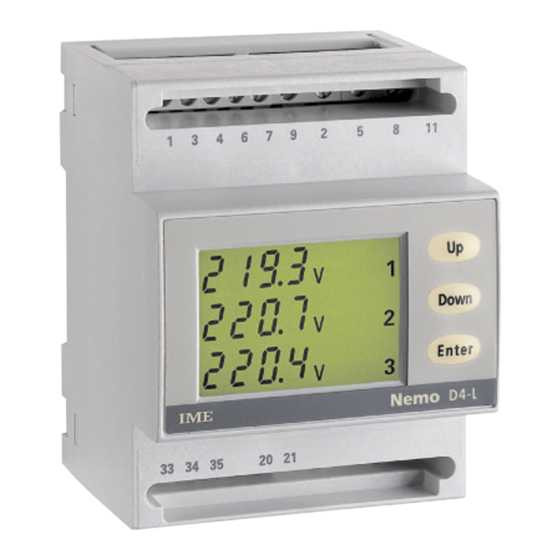
Nemo D4-L
107 0 57
ISTRUZIONI PER L'INST LL ZIONE
Lo strumento non necessita di particolari accorgimenti di installazione meccanici o elettrici.
Prima di procedere alla installazione, verificare che i dati di targa (tensione, corrente, fre-
quenza) corrispondano a quelli effettivi di rete.
PROGR MM ZIONE
L'accesso alla programmazione è protetto da una chiave software costituita da una combina-
zione numerica a 4 cifre. lla richiesta di ingresso in programmazione, lo strumento chiede
all'operatore di inserire, tramite tastiera, la combinazione di accesso, consentendo o negan-
do la possibilità di modifica dei parametri in funzione del codice impostato.
La programmazione è suddivisa su due livelli (con differenti chiavi d'accesso)
LIVELLO 1
Password 1000
= tipo inserzione, tipo potenza media, tempo di media, contrasto display,
comunicazione RS485 o uscita impulsi.
zzeramenti di: picco corrente media, picco potenza media, contaore, energia parziale.
LIVELLO 2
Password 2001
= rapporto trasformazione T e TV esterni
Per la programmazione vengono utilizzati i 3 tasti posti sul frontale:
DOWN + ENTER ingresso programmazione
ENTER conferma dati
DOWN spostamento cursore
UP incremento valore impostato
I
In fase di programmazione, DOWN + ENTER uscita programmazione (senza salvataggio
modifiche)
Nei casi in cui la programmazione è impostabile a passi fissi (es. tipo connessione, azzeramen-
to valori, ecc) i tasti DOWN e UP permettono di selezionare i valori disponibili.
Cod. MF6FT...
Non è possibile accedere direttamente al livello 2 di programmazione, ma solo al termine
della programmazione livello 1.
P R METRI PROGR MM BILI
• P SSWORD 1000
CONNESSIONE
ISTRUMENTI MISURE ELETTRICHE SpA
Lo strumento può essere utilizzato per inserzione su linea monofase o trifase (3 o 4 fili).
Scegliere il tipo di inserzione desiderata e rispettare scrupolosamente nei cablaggi lo schema
di inserzione. Una inesattezza nei collegamenti è inevitabilmente causa di misure falsate o di
danni allo strumento.
La configurazione dell'ingresso, deve essere completata con la programmazione da tastiera
del tipo di inserzione selezionato e degli eventuali rapporti T e TV esterni.
Via Travaglia 7
Inserzioni realizzabili:
20094 CORSICO (MI)
1n1E
schema
S1000/220 linea monofase
ITALIA
3-2E
schema
S1000/213 linea trifase 3 fili, 2 sistemi ron
Tel. +39 02 44 878.1
3-3E
schema
S1000/282 linea trifase 3 fili, 3 sistemi
3n3E
schema
S1000/212 linea trifase 4 fili
www.imeitaly.com
info@imeitaly.com
TTENZIONE! accertarsi della esatta corrispondenza tra lo schema di inserzione utilizzato
e la programmazione del tipo inserzione effettuata da tastiera.
10/11
VERIFIC SEQUENZ F SI
Premendo il tasto NT R (in una qualsiasi pagina di visualizzazione) si effettua un con-
trollo del corretto collegamento delle voltmetriche (sequenza fasi). Se il collegamento è
corretto, la visualizzazione non cambia.
Se il collegamento è errato appare la visualizzazione RR 123. In questo caso occorre cor-
reggere il collegamento delle voltmetriche e ripetere la verifica fino ad ottenere l'esatta
sequenza.
TTENZIONE! Una errata sequenza fasi è causa di errori di misura.
ENERGI
zzeramento: energia attiva parziale
POTENZ MEDI / CORRENTE MEDI
Tempo integrazione: 5, 8, 10, 15, 20, 30, 60 minuti
Potenza associata: attiva, reattiva, apparente
zzeramento: valore massimo potenza media e corrente media
CONT ORE
zzeramento: ore, minuti di funzionamento
USCIT IMPULSI (dove prevista)
Energia associata: attiva o reattiva
Peso impulsi: 1imp/0,1kWh - 1imp/kWh - 1imp/10kWh - 1imp/100kWh (kvarh)
Durata impulso: 50 – 100 – 200 – 300ms
COMUNIC ZIONE RS485 (dove prevista)
Indirizzo: 1...255
Velocità comunicazione: 4,8 – 9,6 – 19,2 Kbit/sec
Bit di parità: nessuna - pari - dispari
Tempo massimo fra i caratteri del messaggio: 3...100ms (Time-out)
Normalmente è consigliabile impostare 003 (3ms).
In caso di assenza di comunicazione, nell'abbinamento ad altre interfacce, provare ad
aumentare il valore.
• P SSWORD 2001
R PPORTO TR SFORM ZIONE TR SFORM TORI ESTERNI
Ct= rapporto primario/secondario T (es. T 800/5 Ct=160)
Vt= rapporto primario/secondario TV (es. TV600/100V Vt=6)
TTENZIONE: per inserzione diretta in tensione(senza TV esterno)
impostare Vt=01.0
VISU LIZZ ZIONE
Il menù di visualizzazione è suddiviso in differenti pagine, e varia in funzione del tipo di
inserzione selezionato. Per scorrere le pagine di visualizzazione premere DOWN.
Per ritornare alle pagine precedenti premere UP .
CONT ORE (ore e minuti di funzionamento)
La funzione contaore, conteggio ore e minuti di funzionamento, è attiva quando il dispositi-
vo rileva la presenza della fase L1.
MOUNTING INSTRUCTIONS
The meter does not need any specific mechanical or electrical mounting contrivance.
Before mounting, it is necessary to verify that data on the label (voltage, current, frequency)
correspond to the real network ones.
PROGR MMING
ccess to programming is protected by a software key composed of a 4-digit numeric combi-
nation. When one wants to enter the programming mode, the meter prompts the operator
to type the access combination, allowing or denying, according to the loaded code, the possi-
bility to modify the parameters.
Programming is subdivided on two levels (with different access keys).
LEVEL 1
Password 1000
= connection type, type of average power, average time, display contrast,
RS485 communication or pulse output.
Reset of: average current peak, average power peak, run hour meter, partial energy.
LEVELL 2
Password 2001
= external C.T. and V .T. transformer ratio
For programming are used the 3 keys on the front board:
DOWN + ENTER to enter the programming
ENTER to confirm the data
DOWN to shift the cursor
UP increases the loaded value
During the programming, DOWN + ENTER to leave the programming (without backing up
the modifications)
In the cases where the programming can be loaded by fixed steps (for instance connection
type, value reset, etc.) DOWN and UP keys allow selecting the available values.
It is not possible to directly access to the programming level 2 but only when the pro-
gramming level 1 is over.
PROGR MM BLE P R METERS
• P SSWORD 1000
CONNECTION
The meter can be connected with single-phase or 3-phase lines (3 or 4 wires).
Choose the desired connection and, in the wiring, scrupulously respect the wiring diagram.
n error in connection unavoidably leads to wrong measurements or damages to the meter.
The input configuration must be completed with the keyboard programming of the chosen
connection type as well as of any external current and voltage transformer ratios.
Possible connections:
1n1E
S1000/220 single-phase line
wiring diagram
3-2E
wiring diagram
S1000/213 3-phase line, 3 wires, 2 ron systems
3-3E
wiring diagram
S1000/282 3-phase line, 3 wires
3n3E
wiring diagram
S1000/212 3-phase line, 4 wires
W RNING! Pay attention that the used wiring diagram meets the keyboard-
programming configuration.
PH SE SEQUENCE CHECKING
Pressing NT R key (in any of the display pages) you can check the correct connection of
the voltmetric (phase sequence).
If the connection is right, the display doesn't change.
If the connection is wrong, rr 123 is displayed. In the case you have to modify the vol-
tmetric connection and repeat the checking until you get the correct sequence.
TTENTION!
wrong phase sequence may lead to measuring errors.
ENERGY
RESET: partial active energy
POWER DEM ND / CURRENT DEM ND
Delay time: 5, 8, 10, 15, 20, 30, 60 minutes
Combined power: active, reactive, apparent
Reset: power max demand and current demand
RUN HOUR METER
Reset: working hours and minutes
PULSE OUTPUT (where applicable)
Combined energy: active or reactive
Pulse frequency: 1imp/0,1kWh - 1imp/kWh - 1imp/10kWh - 1imp/100kWh (kvarh)
Pulse duration: 50 – 100 – 200 – 300ms
RS485 COMMUNIC TION (where applicable)
ddress: 1...255
Baud rate: 4,8 – 9,6 – 19,2 Kbit/sec
Parity bit: none - even - odd
Time-out: 3...100ms
It is normally advisable to load 003 (3ms).
If in connecting the meter with other interfaces the communication is lacking, try to increase
the value.
• P SSWORD 2001
C.T. – V.T. TR NSFORMER R TIO
Ct= current transformer primary/secondary ratio (ex. CT 800/5 Ct=160)
Vt= voltage primary/secondary transformer ratio (ex. VT 600/100V Vt=6)
W RNING: for voltage direct connection
(without external voltage transformer)
, load
Vt=01,0
DISPL Y
Display menu is subdivided into different pages and it changes according to the selected con-
nection type. To scroll the display pages press DOWN.
To return to the previous pages press UP.
HOUR METER (working minutes and hours)
Run hour function, working minutes and hour counting, is operating when the device
detects L1 phase.
10780857
Advertisement

Related Manuals for IME Nemo D4-L


Summary of Contents for IME Nemo D4-L
- Page 1 Nemo D4-L 107 0 57 INSTRUCTIONS POUR L’ INST LL TION INST LL TION SCHEMI D’INSERZIONE • WIRING DI GR MS • SCHEM S DE R CCORDEMENT • NSCHLUßBILD ISTRUZIONI PER L’INST LL ZIONE MOUNTING INSTRUCTIONS L’appareil ne nécessite pas de soins particuliers pour son installation mécanique et électrique.
- Page 2 VISU LIZZ ZIONE • DISPL Y • FFICH GE • NZEIGE PROGR MM ZIONE • PROGR MMING • PROGR MM TION • PROGR MMIERUNG PASSWORD 1 0000 1000 Tensione di fase Tensione concatenata Tensione - Corrente Password 1000 PASSWORD 1 Indirizzo 1...255 Phase voltage Linked voltage...
- Page 3 INSTRUCTIONS POUR L’ INST LL TION INST LL TION L’appareil ne nécessite pas de soins particuliers pour son installation mécanique et électrique. Das Gerät benötigt keine speziellen elektrischen oder mechanischen Installationsvorberei- vant de procéder à l’installation, il faut vérifier que les données indiquées sur la plaque tungen.
- Page 4 SCHEMI D’INSERZIONE • WIRING DI GR MS • SCHEM S DE R CCORDEMENT • NSCHLUßBILD S 1000/220 S 1000/213 INPUT OUTPUT AUX. INPUT OUTPUT AUX. RS 485 RS 485 SUPPLY SUPPLY CURRENT VOLTAGE VOLTAGE CURRENT GND Rx / Tx GND Rx / Tx –...
- Page 5 Nemo D4-L 107 0 57 Cod. MF6FT... ISTRUMENTI MISURE ELETTRICHE SpA Via Travaglia 7 20094 CORSICO (MI) ITALIA Tel. +39 02 44 878.1 www.imeitaly.com info@imeitaly.com 10/11 10780857...
-
Page 6: Mounting Instructions
ISTRUZIONI PER L’INST LL ZIONE MOUNTING INSTRUCTIONS Lo strumento non necessita di particolari accorgimenti di installazione meccanici o elettrici. The meter does not need any specific mechanical or electrical mounting contrivance. Prima di procedere alla installazione, verificare che i dati di targa (tensione, corrente, fre- Before mounting, it is necessary to verify that data on the label (voltage, current, frequency) quenza) corrispondano a quelli effettivi di rete. - Page 7 VISU LIZZ ZIONE • DISPL Y • FFICH GE • NZEIGE Tensione di fase Tensione concatenata Phase voltage Linked voltage Tension de phase Tension composée Phasenspannung Verkettete Spannung Corrente di fase Corrente di fase Phase current Phase current Courant de phase Courant de phase Phasenstrom Phasenstrom –...
- Page 8 PASSWORD 1 0000 Tensione - Corrente Password 1000 PASSWORD 1 Voltage - Current Password 1000 Tension – Courant MOT-CLE 1 Mot-clé 1000 Spannung – Strom Kennwort 1000 KENNWORT 1 Potenza attiva, reattiva, apparente Active, reactive, apparent power Puissance active - réactive, apparente Energia attiva parziale Azzeramento: NO Wirk- Blind- und Scheinleistung...
- Page 9 PROGR MM ZIONE • PROGR MMING • PROGR MM TION • PROGR MMIER 1000 Indirizzo 1...255 Address 1...255 Adresse 1...255 Adresse 1...255 COMUNICAZIONE RS485 Velocità comunicazione Azzeramento: SI Reset: YES Baud rate Remise à zéro: OUI Vitesse de communication Nullstellung: JA Kommunikationsgeschwindigk RS485 COMMUNICATION Bit parità...
- Page 10 RUNG 4,8Kbit/s 9,6Kbit/s 19,2Kbit/s ..Rettiva Attiva Reactive Active Réactive Active Blind Wirk 1imp/0,1kWh 1imp/kWh 1imp/10kWh 1imp/100kWh 100ms 200ms 50ms 300ms ..1000 2000 2000 2001 0000 2000 2000 0001 0002 0001 0003 0001 0004 001.0 001.1 001.0 001.2 001.3 10780857...
Need help?
Do you have a question about the Nemo D4-L and is the answer not in the manual?
Questions and answers