Nice POA1 Instructions And Warnings For Installation And Use
Hide thumbs
Also See for POA1:
- Instructions and warnings for the fitter (112 pages) ,
- Instructions and warnings for installation and use (96 pages)
Table of Contents
Advertisement
Quick Links
Advertisement
Table of Contents

Related Manuals for Nice POA1


Summary of Contents for Nice POA1
- Page 1 POA1 Control unit EN - Instructions and warnings for installation and use...
-
Page 3: Table Of Contents
5.2 - PROGRAMMABLE FUNCTIONS ......4 The POA1 control unit has been designed to control POP 24 V electromechan- 5.2.1 - Direct programming . -
Page 4: Preliminary Checks For Installation
• Activation of the “PHOTO 1” pair of photocells stops both the opening and 2.3 - Electrical connections closing manoeuvres. IMPORTANT! • Activation of the “PHOTO2” pair of photocells (connected to the suitably pro- – All electrical connections must be made with the unit disconnected from grammed AUX input) has no effect during closing while they invert movement the mains power supply and with the buffer battery disconnected, if pres- during opening. -
Page 5: Type Of Alt Input
(note 4) On the successful completion of the various controls, start the automatic search system phase for the limit switches. This work is necessary as the POA1 control unit must “measure” how long the opening and closing manoeuvres Notes to Table 1: take This procedure is completely automatic and detects the mechanical open- Note 1 –... -
Page 6: Testing And Commissioning
Led P2 flashes The additional or optional devices must undergo a specific test for functionality M1 current sensitivity device triggering and correct interaction with POA1. Refer to the instruction manuals of the indi- M2 current sensitivity device triggering vidual devices. -
Page 7: First Level Programming: Second Part
of the lower leaf motor compared with the upper one This is necessary in The P1, P2 and P3 buttons are used for all the programming phases, while the order to prevent the leafs from getting stuck. There is always a standard delay 5 LEDs (L1, L2…L5) indicate the selected parameter. -
Page 8: First Level Programming: Functions
5.3.1 - Level one programming: functions has been selected, short flashes indicate the function has been deactivated; long flashes indicate the function has been activated. Press P3 to pass from At level 1, the functions can be enabled or disabled. At level one, LED P1 is part one programming to part two programming, and vice-versa. -
Page 9: Example Of First Level Programming
TABLE C1 - Delete memory 01. Switch the power supply to the control box off, and wait until all the LEDs have gone off (remove fuse F1 if necessary) 02. Press P1 and P2 on the board down and keep them pressed down 03. -
Page 10: Programming Diagrame
5.3.6 - Programming diagram This figure also shows the functions and parameters either as they were initially or following total memory deletion. The following figure shows the complete programming diagram of the functions and relative parameters. Normal operation Led P1 Slow flashing Photo Photo Step step... -
Page 11: Further Details: Accessories
Step by step N° 2 AUX (reset value: Partially Open 1) As the POA1 control unit is electronic it requires no particular maintenance. N° 3 “Open only” However, at least every six months the efficiency of the entire system must be N°... -
Page 12: Technical Characteristics Of The Product
EC DECLARATION OF CONFORMITY Note - The contents of this declaration correspond to declarations in the last revision of the official document deposited at the registered offices of Nice Spa available before this manual was printed. The text herein has been re-edited for editorial purposes. -
Page 13: Radio Receiver: Smxi - Smixs
smxi - smixs 0682 radio receiver The receiver features 4 outputs, all available on the underlying connector. To find out which function is performed by each output, see chapter 6.1. PRODUCT DESCRIPTION During the transmitter code memorisation phase, one of these two options may be chosen: Mode I - Table B1: Each transmitter button activates the corresponding out- SMXI and SMXIS are 4-channel radio receivers for control units equipped with... -
Page 14: Deleting All Transmitters
TECHNICAL CHARACTERISTICS OF THE PRODUCT WARNINGS: • All technical characteristics stated refer to an ambient temperature of 20°C (±5°C). • Nice S.p.a reserves the right to modify the product at any timee, while maintaining the same functionalities and intended use. • The range of the transmitters and the reception capacity of the receivers may be subject to interference that may alter their performance. -
Page 15: Images
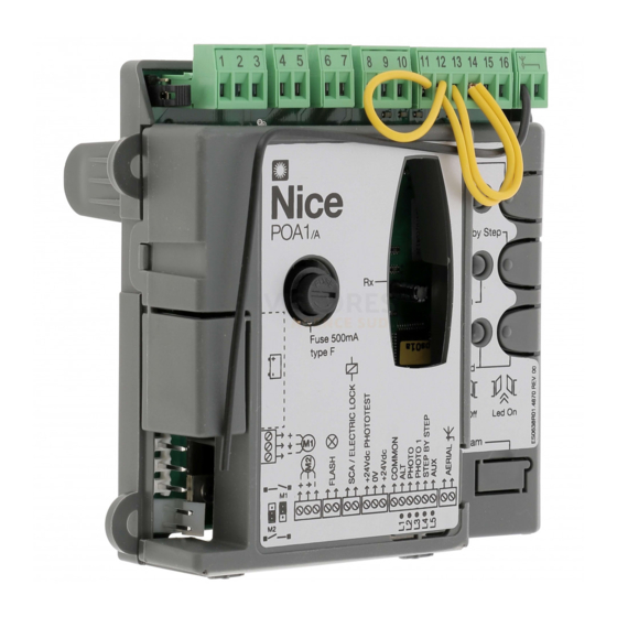
Images Immagini Images Imágenes Bilder Zdjęcia Afbeeldingen... - Page 16 EN - E = Electric jumper DE - E = Brücke IT - E = Ponticello elettrico PL - E = Mostek elektryczny FR - E = Cavalier électrique NL - E = Elektrische ES - E = Conexión eléctrico geleidingsbrug 1 2 3 8 9 10 11 12 13 14 15 16...
- Page 17 Connection with “Everything in stand by” active (energy saving) IT - Collegamento con “Stand by tutto” attivo (risparmio energetico) FR - Connexion avec « Stand-by total » actif (économie d’énergie) ES - Conexión con “Stand by todo” activo (ahorro energético) Anschluss mit aktivem “Stand by - alles”...
- Page 18 Connection without “Everything in stand by” with “Phototest” IT - Collegamento senza “Stand by tutto” con “Fototest” FR - Connexion sans “Stand by todo” et avec « phototest » ES - Conexión sin “Stand by todo” con “Fototest” Ohne “Stand by - alles” und ohne “Phototest” PL - Połączenie bez funkcji “Stand by całego urządzenia”...
- Page 19 STEP BY STEP NC NO NO NC 12 V ~ 33 V max 5 W max 25 VA 8,2KΩ 8,2KΩ 8,2KΩ With “Everything in stand by” active connect terminal no. 8 and Bei aktivem “Stand by - alles”, die Klemme Nr. 8 und und nicht 11 not no.
- Page 21 Ph. +351.21.922.82.10 Ph. +39.049.87.01.05.1 Nice Australia infomarseille@fr.niceforyou.com Fax +351.21.922.82.19 Fax +39.049.87.07.63.8 Wetherill Park Australia info@pt.niceforyou.com infopd@niceforyou.com Ph. +61.(0)2.96.04.25.70 Nice France Rhône Alpes Fax +61.(0)2.96.04.25.73 Nice Roma Decines Charpieu France Nice Romania info@au.niceforyou.com Roma Italia Cluj Napoca Romania Ph. +33.(0)4.78.26.56.53 Ph. +39.06.72.67.17.61 Ph./Fax +40.(0)264.453.127...
Need help?
Do you have a question about the POA1 and is the answer not in the manual?
Questions and answers