
Related Manuals for Meinberg microSync RX800/AD10DC20


Summary of Contents for Meinberg microSync RX800/AD10DC20
- Page 1 TECHNICAL REFERENCE microSync RX800/AD10DC20 August 11, 2022 Meinberg Funkuhren GmbH & Co. KG...
-
Page 3: Table Of Contents
Network Configuration via Web Interface ......8.1.3 Network Configuration via Meinberg Device Manager ..... - Page 4 Start of Operation with meinbergOS Web Interface ..... . 8.2.2 Start of Operation with Meinberg Device Manager Software ....9 Technical Appendix Technical Specifications GNSS Receiver .
-
Page 5: Imprint
1 Imprint 1 Imprint Meinberg Funkuhren GmbH & Co. KG Lange Wand 9, 31812 Bad Pyrmont, Germany Phone: + 49 (0) 52 81 / 93 09 - 0 Fax: + 49 (0) 52 81 / 93 09 - 230 Website: https://www.meinbergglobal.com... -
Page 6: Microsync Introduction
• High performance (S)NTP server • Redundant power supply • Different Oscillator options for advanced holdover performance • Meinberg Device Manager for configuration and status monitoring • Three-year manufacturer‘s warranty • Unlimited technical support including firmware updates Date: August 11, 2022... -
Page 7: Technical Specifications Microsync Chassis
3 Technical Specifications microSync Chassis 3 Technical Specifications microSync Chassis Protection Rating: IP30 Temperature Range (Operation) 0 ... 50 C (32 ... 122 F) Temperature Range (Storage) -20 ... 70 C (-4 ... 158 F) Relative humidity 5 to 95% (non-condensing) at 40 C (104 F). (Operation) Operating Altitude: up to 4,000 m (13,123 ft) above sea level... -
Page 8: Important Safety Information
4 Important Safety Information 4.1 Important Safety Information and Safety Precautions The following safety information must be observed whenever the device is being installed or operated. Failure to observe this safety information and other special warnings or operating instructions in the product manuals constitutes improper usage and may violate safety standards and the manufacturer’s requirements. -
Page 9: Used Symbols
4 Important Safety Information 4.2 Used Symbols The following symbols and pictograms are used in this manual. Pictograms are used in particular to indicate potential hazards in all hazard categories. Symbol Beschreibung / Description IEC 60417-5031 Gleichstrom / Direct current IEC 60417-5032 Wechselstrom / Alternating current IEC 60417-5017... -
Page 10: Product Documentation
Detailed product documentation is provided on a USB flash drive delivered with the system. The manuals can also be downloaded from the Meinberg website at https://www.meinbergglobal.com, where you can enter your system name into the search box at the top of the page to find the relevant manual. Alternatively, contact Meinberg Support for further assistance. -
Page 11: Safety During Installation
4 Important Safety Information 4.4 Safety during Installation WARNING! Pre-Operation Procedures and Preparation for Use This mountable device has been designed and examined in accordance with the requirements of the standard IEC 62368-1 "Audio/Video, Information and Communication Technology Equipment - Part 1: Safety Requirements". When the mountable device is to be used as part of a larger unit (e.g., electrical enclosure), there will be additional requirements in the IEC 62368-1 standard that must be observed and complied with. - Page 12 = 90 - 250 V Faulty shielding or cabling and improperly connected plugs are a health & safety risk (risk of injury or death due to electrical shock) and may damage or even destroy your Meinberg device or other equipment.
- Page 13 4 Important Safety Information AC Power Supply DC Power Supply The device is a Protection Class 1 device and In accordance with IEC 62368-1, it must be • • may only be connected to a grounded outlet possible to disconnect the appliance from the (TN system).
-
Page 14: Connection Of Protective Earth Conductor/Grounding
4.5 Connection of Protective Earth Conductor/Grounding ATTENTION! In order to ensure that the device can be operated safely and to meet the requirements of IEC 62368-1, the device must be correctly connected to the protective earth conductor via the protective earth connection terminal. If an external ground connection is provided on the housing, it must be connected to the grounding busbar (earthing busbar) for safety reasons before connecting the power supply. -
Page 15: Safety During Operation
4 Important Safety Information 4.6 Safety During Operation WARNING! Avoiding Short-Circuits Protect the device against all ingress of solid objects or liquids. Ingress presents a risk of electric shock or short-circuiting! Ventilation Slots Ensure that the ventilation slots are clean and uncovered at all times. Blocked ventilation slots may cause heat to be trapped in the system, resulting in overheating. -
Page 16: Safety During Maintenance
(approx. 60 N) presents a risk of injury to the hands. Information on which components are approved for installation can be obtained from Meinberg Technical Support. The device must not be opened. Repairs to the device may only be performed by the manufacturer or authorized personnel. -
Page 17: Handling Of Batteries
The battery is used to power components such as the RAM and the reserve real-time backup clock for the reference clock. If the battery voltage drops below 3 V DC, Meinberg recommends having the battery replaced. If the battery voltage drops below the specified minimum, the following behavior may be... -
Page 18: Safety Information For Sfp Modules
fiber optic or electrical connection. The safety information below must be read and heeded before installing an SFP module in a Meinberg device, before setting up a Meinberg device equipped with SFP modules for use, or before performing maintenance on such a Meinberg device. -
Page 19: Cleaning And Care
4 Important Safety Information 4.10 Cleaning and Care ATTENTION! Never clean the device using liquids! Water ingress is a significant safety risk for the user (e.g., electric shock). Liquids can cause irreparable damage to the electronics of the device! The ingress of liquids into the device chassis may cause short circuits in the electronic circuitry. -
Page 20: Return Of Electrical And Electronic Equipment
When disposing of your old equipment, please use the national return or collection systems available to you. Alternatively, you may contact Meinberg, who will provide further assistance. The return of electronic waste may not be accepted if the device is soiled or contaminated in such a way that it potentially presents a risk to human health or safety. -
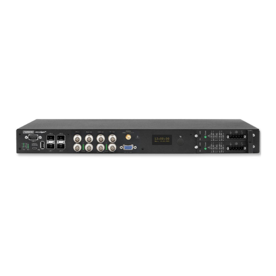
Page 21: Microsync Rx800/Ad10Dc20 Connectors
5 microSync RX800/AD10DC20 Connectors 5 microSync RX800/AD10DC20 Connectors 1 17 1 1 1 1 1 1 1 15 1 13 1 11 5.1 AC/DC Power Supply Important! Hotplug It is possible to remove or install power supplies from the system housing during operation. - Page 22 The status LED of the new power supply should now light up. The "OK" status must be displayed in the system’s web interface. Checking Power Status The status of the power supplies can be observed in the program Meinberg Device Manager under "Status System Status". Date: August 11, 2022...
- Page 23 5 microSync RX800/AD10DC20 Connectors AD10 - AC/DC Power Supply Connector Type: 5-pol. DFK Pin Assignment: 1: N/- 2: not connected 3: PE (Protective Earth) 4: not connected 5: L/+ Input Parameter ———————————————————————————— Nominal Voltage Range: 100-240 V 100-200 V Maximum Voltage Range:...
- Page 24 DC20 - DC Power Supply Connector Type: 5pin DFK Pin Assignment: 1: not connected 2: V 3: PE (Protective Earth) 4: V 5: not connected Input Parameter ———————————————————————————— Nominal Voltage Range: 24-48 V Maximum Voltage Range: 20-60 V Nominal Current: 2.10 A Output Parameter ————————————————————————————...
-
Page 25: Microsync Oled Display
(Devman), which should support all current functions, and the commit value, which is an internal identification for the software, are displayed. Target : 0x310 • System type - e.g.: microSync RX800/AD10DC20 Devman : 6.2 • SN - serial number Commit : 86AD960 •... - Page 26 figuration made via the display has been changed externally. This case occurs if e.g. the IP address, DHCP On which was configured via the display, is changed by (*) external changed using the Meinberg Device Manager later. IP Address: 166.030.044.002/16 Gateway: • DHCP - On / Off...
-
Page 27: Gnss Antenna
5 microSync RX800/AD10DC20 Connectors 5.3 GNSS Antenna Antenna type Multi GNSS L1 antenna with integrated lightning protection Receiver type 72-channel GPS/Galileo/Glonass/ Beidou Frequency band L1 / E1 / B1 , 1575.42 +- 10 MHz / 1602-1615 MHz Signal gain 40 dB Antenna gain: 3.5 dBic /... -
Page 28: Ltc/Gpio
5.4 LTC/GPIO Signal: LTC-Reader (25 fps) Signal level: TTL; 2,5 V (MARK/SPACE) at 50 Ohm Pin Assignment: LTC out - LTC symmetric Lo Pot. Output LTC_out + LTC symmetric HI Pot. Output LTC_in + LTC symmetric HI-Poti. Input LTC in - LTC symmetric Lo Pot. Input LTC TTL in LTC, TTL-Level, Input DARS + DARS symmetric Hi Pot. -
Page 29: Status Leds - Vsg Signals
5 microSync RX800/AD10DC20 Connectors 5.6 Status LEDs - VSG Signals Status indicator LED St: Status of the internal VSG LED In: Synchronization status LED A: Status of the blackburst output LED B: Status of the LTC output The status messages of the LEDs result as follows:. -
Page 30: Dars Output
5.7 DARS Output Output signal: DARS Signal level: TTL; 2.5 V into 75 ohms Signal type: Base frequencies: 44.1 kHz and 48 kHz Connection type: BNC female connector Cable: Coaxial cable, shielded 5.8 Word Clock Output Output signal: Word Clock Signal level: TTL;... -
Page 31: Blackburst Input
5 microSync RX800/AD10DC20 Connectors 5.9 Blackburst Input Input Signal Black Burst (PAL) Input with VITC Reader Input with Prescaler mode (Frequency only) Signal level: 300 mV into 75 ohms (unbalanced) Time Code Formats: PAL SMPTE259M / ITU-R BT.470-6 SMPTE12M-1 / SMPTE ST309M... -
Page 32: Status Leds - Input Signals
5.11 Status LEDs - input signals Status indicator LED B: Status of the blackburst input signal. LED L: Status of the LTC input signal LED C: Status of the Word Clock input signal LED P: Status of the PPS input signal The status messages of the LEDs are as follows:. -
Page 33: Pulse Per Second Input
5 microSync RX800/AD10DC20 Connectors 5.12 Pulse Per Second Input Input signal PPS (pulse per second) Signal level: Pulse lenght: 5 s, active high Connection type: BNC, female Cable: Coaxial cable, shielded 5.13 Word Clock Input Input signal: Word Clock Input with... -
Page 34: Usb Interface
Available SFP Modules SFP Tranceivers Recommended and Tested by Meinberg Output Type Manufacturer Designation Multi Mode: Avago AFBR-5710PZ Finisar FTLF8524P3BNL Single Mode: Avago AFCT-5710PZ Finisar FTLF1318P3BTL RJ-45: Avago ABCU-5740RZ Finisar FCLF8521P2BTL Warning! Prevention of Eye Injuries • Fiber optic SFP modules that are not compliant with the definition of a Class 1 laser in accordance with IEC standard 60825-1 may emit radiation capable of causing eye injuries. -
Page 35: Status Indicators - Cpu And Receiver
5 microSync RX800/AD10DC20 Connectors 5.16 Status Indicators - CPU and Receiver CPU: —————————————————————————– R (Receiver) green: The reference clock (e.g. build-in GNS181) provides a valid time red: the reference clock does not provide a valid time T (Time Service) green: NTP is synchronized to the reference clock, e.g. -
Page 36: Rs-232 Comx Timestring
5.17 RS-232 COMx Timestring Data transfer: serial Baudrate/framing: 19200 / 8N1 (default) Time-string: Meinberg Standard (default) Assignment: Pin 2: RxD (receive) Pin 3: TxD (transmit) Pin 5: GND (ground) Connector: 9pin D-SUB male Cable: data cable (shielded) PC connector 1:1... -
Page 37: Information On Satellite Reception
Your system is fitted with the GNS181, a 72-channel satellite receiver clock which serves as a high-accuracy time reference and high-precision frequency reference for your Meinberg system and is designed to receive signals from the United States GPS (Global Positioning System), Russian GLONASS (GLObal NAvigation Satellite System), the European Galileo system, and the Chinese BeiDou system. -
Page 38: Time Zones And Daylight Saving Time
6.2.1 Time Zones and Daylight Saving Time GPS System Time is a linear timescale that was synchronized with the international UTC timescale (Coor- dinated Universal Time) when the satellite system became operational in 1980. Since it has entered service, however, several leap seconds have been introduced to the UTC timescale to adjust UTC time to irregularities in the Earth’s rotation. -
Page 39: Gnss Antenna Installation
7 GNSS Antenna Installation 7 GNSS Antenna Installation Two different antennas are available for our combined GPS/GLONASS/Galileo/BeiDou satellite receivers that are each designed to fulfill different tasks or applications. The active Multi-GNSS L1 antenna is the standard accessory and can receive signals from the GPS, GLONASS, Galileo, and BeiDou satellite systems. -
Page 40: Installation Of The Multi-Gnss Antenna
7.1 Installation of the Multi-GNSS Antenna Danger! Do not mount the antenna without an effective fall arrester! Danger of death from falling! • Ensure that all necessary safety measures are taken when installing an antenna! • In particular, never work without an effective fall arrester! Danger! Do not work on the antenna system during thunderstorms! Danger of death from electric shock! - Page 41 Case Example 4: If the cable leading from the point of entry into the building to the Meinberg system is laid together with other cables (for example in a cable duct alongside high-voltage cables), transient voltages may "leak" into the antenna cable, causing damage to your system.
- Page 42 Type-N (Male) If installed in a waterproof housing, the MBG S- Type-N (Female) PRO can be installed outdoors. However, Meinberg recommends installing the surge protector indoors—as closely to the entrance point of the antenna cable as possible—in order to minimize the risk of surge dam- age (such as that caused by lightning strike).
- Page 43 7 GNSS Antenna Installation Grounding Conductor To ground the antenna cable, connect the surge protec- to Grounding Busbar tor to a grounding busbar using a grounding conductor Conductor of diameter approx. 1.5 mm (see illustration). attached to surge protector As short as possible Once installation is complete, connect the other end of the antenna cable to the surge protector female con- nector.
- Page 44 The splitter may be installed at any location between the surge protector and the receivers. Information: It is not possible to directly connect a Meinberg GPS antenna/converter unit to an L1 antenna splitter. Antenna Receiver...
-
Page 45: Assembly Of The Rv-76G Gps/Glonass Antenna For Mobile Applications
7 GNSS Antenna Installation 7.2 Assembly of the RV-76G GPS/GLONASS Antenna for Mobile Applications Installation of the Antenna Further Information on the Product Detailed specifications are provided in the manufacturer’s data sheet. Source: Datasheet RV-76G_Catalog_V1.0_20130502 (Sanav) https://www.meinbergglobal.com/download/docs/other/rv-76g_en.pdf Download: microSync Date: August 11, 2022... -
Page 46: Starting Of Operation
There are three ways to perform the basic network configuration of your microSync: • Configuration via a serial connection, see Chapter 8.1.1. • Configuration via the Web Interface, see Chapter 8.1.2. • Configuration via Meinberg Device Manager, see Chapter 8.1.3. Date: August 11, 2022 microSync... -
Page 47: Network Configuration Via Serial Connection
8 Starting of Operation 8.1.1 Network Configuration via Serial Connection The initial network configuration of the microSync can also be performed via a serial USB connection. You can connect the USB port on the PC with the micro-USB port of the microSync using a standard USB cable (Micro-USB Type B to USB-A). - Page 48 Web Interface or Meinberg Device Manager. Information: If the microSync’s network configuration has already been previously performed using the Web Interface or Meinberg Device Manager, you will not be able to do this using mbgOSWizard.sh. Date: August 11, 2022 microSync...
-
Page 49: Network Configuration Via Web Interface
8 Starting of Operation 8.1.2 Network Configuration via Web Interface The network configuration for the microSync can be performed via the Web Interface. In its factory-shipped state, the microSync has the following network configuration: Network Port LAN 0 192.168.19.79 IPv4 Address: 255.255.255.0 Subnet Mask: Gateway:... - Page 50 As soon as the Dashboard appears, click on the "Configuration" section in the Header Bar, then select the "Network" tile. Be sure in particular to correctly configure the network settings for the intended management interface ("Interfaces" tab) to ensure that it is accessible within the subnet. Once you have performed the configuration, click on "Save"...
-
Page 51: Network Configuration Via Meinberg Device Manager
The software is delivered on the USB stick included in the scope of delivery and does not need to be in- stalled or copied on the PC. The Meinberg Device Manager can be started directly from the USB data carrier. - Page 52 DHCP: Disabled The PC on which Meinberg Device Manager is used must be able to establish a network connection with the above address in the appropriate subnet. If the PC’s network configuration or the network’s topology or addressing prevent a connection from being established with the microSync, the network configuration of the PC will need to be (temporarily) changed and a different physical connection may need to be established (e.g.
- Page 53 8 Starting of Operation If the inserted microSync cannot be found via the automatic search, the Add Device button can be used to set up the connection manually. Manual Setup Select the connection type microSyncHR, microSyncRX (Network). Then enter the IPv4 address of the microSync (192.168.19.79).
-
Page 54: Initial Start Of Operation
(Figure 8.1). The default settings are: admin Username: Password: timeserver Further information about the meinbergOS web interface in the chapter "The meinbergOS Web Interface" to be found in the microSync installation manual: https://www.meinberg.de/download/docs/manuals/english/microsync.pdf Date: August 11, 2022 microSync... -
Page 55: Start Of Operation With Meinberg Device Manager Software
8.2.2 Start of Operation with Meinberg Device Manager Software First install the Meinberg Device Manager software supplied on the USB stick. After the setup, start the program. If you do not want to perform a setup on your computer, you can start the portable version of the Meinberg Device Manager software directly on the USB stick: USB Drive/Software/MbgDevMan/mbgdev- man_portable/mbgdevman.exe. - Page 56 User and Password fields are already filled out. Silent Login You have the option that the Meinberg Device Man- ager does not ask for a user name and password every time you log in. Custom Alias Assign a custom alias for better identification of indi-...
-
Page 57: Technical Appendix
Framing: 7E1, 7E2, 7N2, 7O1, 7O2, 8E1, 8N1, 8N2, 8O1 Default Setting: COM 0: 19200, 8N1 Meinberg Standard time string, per second Time Code Outputs: Unbalanced modulated sine wave signal: (MARK), 1 V (SPACE) into 50 PWM DCLS-signal: TTL into 50... - Page 58 GNS Receiver (GNS181) Type of receiver: GPS/GLONASS/Galileo/BeiDou receiver Number of channels: 72 Frequency band: GNSS L1 GPS: 1575.42 10 MHz GLONASS: 1602-1615 MHz Galileo: 1542.5 MHz BeiDou: 1561.09 MHz Antenna: Combined GPS/GLONASS antenna 3 dB Bandwidth: 1590 30 MHz Impedance: Gain: 4 dB Cable length:...
-
Page 59: Configuration Options
9 Technical Appendix 9.2 Configuration Options Receiver Options RECEIVER TYPE SIGNAL TYPE VALUE CONNECTOR Meinberg GPS IF, 12-channel IF (Meinberg Antenna)) 15 V DC Meinberg GNS-UC GPS/Galileo IF IF (Meinberg Antenna)) 15 V DC GNSS (GPS, GLONASS, Galileo, BeiDou), 72-Channel... -
Page 60: Technical Appendix: Gnss Antennas + Accessories
10 Technical Appendix: GNSS Antennas + Accessories 10.1 Information on the 40dB Multi GNSS Antenna GPS L1 / GLONASS L1 / GALILEO E1 / BeiDou B1 Frequency Band GPS, GLONASS, Galileo and BeiDou satellites do not hold a geostationary orbit, but circle the Earth once roughly every 12 hours. -
Page 61: Technical Specifications: Antenna Cable
10.2 Technical Specifications: Antenna Cable The table below shows which coaxial cable types and lengths are supported by Meinberg for each of the receiver types. If you need to purchase a replacement cable at any time, please refer to this table to ensure that you select cable with suitable cutoff... -
Page 62: Technical Specifications: Mbg S-Pro Surge Protection
10.4 Technical Specifications: MBG S-PRO Surge Protection Adapter plug with replaceable gas discharge tube for coaxial signal connections. Connector Type: Type-N connector female/female. The MBG S-PRO set includes a surge protector (Phoenix CN-UB-280DC-BB), a pre-assembled coaxial cable, and a mounting bracket. The coaxial cable surge protector must be installed on the antenna line. - Page 63 10 Technical Appendix: GNSS Antennas + Accessories Max. Discharge Current: (8/20) s Maximum (Core-Shield) 20 kA Rated Pulse Current: (10/1000) s (Core-Shield) 100 A Impulse Discharge Current: (10/350) s, Peak Value I 2.5 kA Output Voltage Limit: At 1 kV/ s (Core-Earth) spike 900 V At 1 kV/ s (Core-Earth) spike 900 V...
-
Page 64: Mbg S-Pro: Physical Dimensions
10.4.1 MBG S-PRO: Physical Dimensions 15,8 10.4.2 Installation and Grounding Date: August 11, 2022 microSync... -
Page 65: Technical Specifications: Rv-76G Gps/Glonass Antenna For Mobile Applications
10 Technical Appendix: GNSS Antennas + Accessories 10.5 Technical Specifications: RV-76G GPS/GLONASS Antenna for Mobile Applications General Information The antenna system RV-76G is the integration of a high performance GPS/GLONASS patch antenna and a state-of-the-art low-noise amplifier into a very low-profile, extremely compact and fully waterproof antenna signal enclosure. - Page 66 Note: When mounted on the 70 mm x 70 mm square base plate Environmental Conditions Operating Temperature: ~40 C +85 C Storage Temperature: ~40 C +90 C Relative Humidity: 95% non-condensing Source: Datasheet gps-glonass_antenna_rv-76g_catalog_v1.pdf (Sanav) https://www.meinberg.de/download/docs/other/rv-76g_en.pdf Date: August 11, 2022 microSync...
-
Page 67: Rohs And Weee
WEEE-compliant fashion, it must be returned to the manufacturer. Any transportation ex- penses for returning this product (at end-of-life) must be covered by the end user, while Meinberg will bear the costs for the waste disposal itself. microSync... -
Page 68: Declaration Of Conformity
12 Declaration of Conformity Declaration of Conformity Doc ID: microSync RX800/AD10DC20-August 11, 2022 Hersteller Meinberg Funkuhren GmbH & Co. KG Manufacturer Lange Wand 9, D-31812 Bad Pyrmont erklärt in alleiniger Verantwortung, dass das Produkt, declares under its sole responsibility, that the product...
Need help?
Do you have a question about the microSync RX800/AD10DC20 and is the answer not in the manual?
Questions and answers