GORMAN-RUPP PUMPS 0 Series Installation, Operation, And Maintenance Manual With Parts List
Hide thumbs
Also See for 0 Series:
Table of Contents
Advertisement
Quick Links
Q
OM−03745−02
May 3, 1999
Rev. A 03-31-10
INSTALLATION, OPERATION,
AND MAINTENANCE MANUAL
WITH PARTS LIST
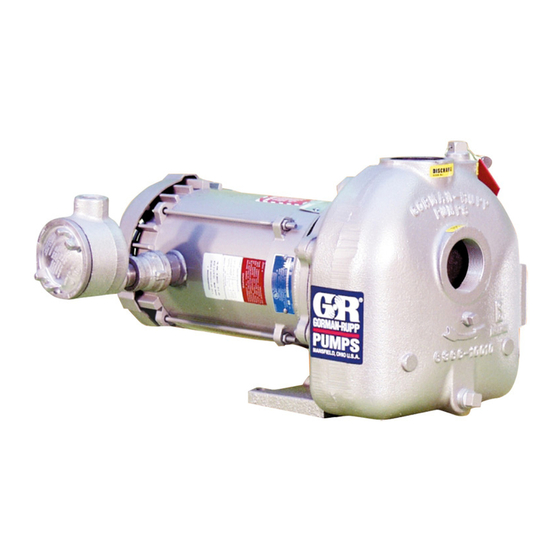
0 SERIES PUMP
MODEL
04E1-GA
THE GORMAN-RUPP COMPANY D MANSFIELD, OHIO
www.grpumps.com
D
GORMAN-RUPP OF CANADA LIMITED
ST. THOMAS, ONTARIO, CANADA
Printed in U.S.A.
e
1999 The Gorman-Rupp Company
Advertisement
Table of Contents

Related Manuals for GORMAN-RUPP PUMPS 0 Series


Summary of Contents for GORMAN-RUPP PUMPS 0 Series
- Page 1 OM−03745−02 May 3, 1999 Rev. A 03-31-10 INSTALLATION, OPERATION, AND MAINTENANCE MANUAL WITH PARTS LIST 0 SERIES PUMP MODEL 04E1-GA THE GORMAN-RUPP COMPANY D MANSFIELD, OHIO www.grpumps.com GORMAN-RUPP OF CANADA LIMITED ST. THOMAS, ONTARIO, CANADA Printed in U.S.A. 1999 The Gorman-Rupp Company...
- Page 2 Register your new Gorman-Rupp pump online at www.grpumps.com Valid serial number and e-mail address required. RECORD YOUR PUMP MODEL AND SERIAL NUMBER Please record your pump model and serial number in the spaces provided below. Your Gorman-Rupp distributor needs this information when you require parts or service. Pump Model: Serial Number:...
-
Page 3: Table Of Contents
TABLE OF CONTENTS INTRODUCTION ..........PAGE I −... - Page 4 TABLE OF CONTENTS (continued) Pump Casing Removal ..........PAGE E −...
-
Page 5: Introduction
Phone: (519) 631−2870 pump. This pump is an 0 Series, enclosed impeller, cen- trifugal model, with straight-in suction and without The following are used to alert maintenance per- a suction check valve. The pump is equipped with sonnel to procedures which require special atten- Victaulic"... -
Page 6: Safety - Section A
0 SERIES OM−03745 SAFETY − SECTION A This information applies to 0 Series power take-off pumps. Refer to the man- ual accompanying the vehicle before at- tempting to begin operation. If this pump is used with volatile and/or flammable liquids, be certain proper... - Page 7 0 SERIES OM−03745 to a boil, build pressure, and cause the pump casing to rupture or explode. After the vehicle is positioned for pump maintenance, block the wheels and set the emergency brake before attempting If this pump is used with volatile and/or...
-
Page 8: Installation − Section Bpage B
0 SERIES OM−03745 INSTALLATION − SECTION B Review all SAFETY information in Section A. formance and safety, be sure to limit the incoming pressure to 50% of the maximum permissible oper- Since pump installations are seldom identical, this ating pressure as shown on the pump perform- section offers only general recommendations and ance curve (see Section E, Page 1). -
Page 9: Preinstallation Inspection Page B
OM−03745 0 SERIES PREINSTALLATION INSPECTION VEHICLE REQUIREMENTS The following instructions apply equally to new in- The pump assembly was inspected and tested be- stallations, rebuilds or retrofits. fore shipment from the factory. Before installation, inspect the pump for damage which may have oc- Tank Preparation curred during shipment. - Page 10 0 SERIES OM−03745 sion jack with custom brackets should be When connecting the universal joint drive shaft as- sembly to a PTO unit, install, support, and align the used to lift and position the pump and drive shaft in accordance with the manufacturer’s gearbox.
-
Page 11: Suction And Discharge Piping
OM−03745 0 SERIES LUGS MUST BE IN LINE, REGARDLESS OF OPERATING ANGLE SHOWN BELOW LUG ALIGN- MENT SHAFTS PARALLEL, ANGLES EQUAL SHAFTS NOT PARALLEL, ANGLES EQUAL Figure 2. Proper Installation And Alignment of Universal Assembly SUCTION AND DISCHARGE PIPING tors, related piping and safety accessories. Some of the accessories are available from Gorman- Rupp as optional equipment. -
Page 12: Piping
0 SERIES OM−03745 SCHEMATIC SYSTEM USING EDUCTOR FOR DISPENSING AND FILLING Figure 3. Typical System Installation Using Educator For Filling And Dispensing SCHEMATIC SYSTEM USING PUMP FOR DISPENSING AND FILLING Figure 4. Typical Installation Using Pump For Filling And Dispensing... -
Page 13: Sealing
OM−03745 0 SERIES suction line to ensure an adequate supply of liquid Sealing to the pump. Since even a slight leak will affect priming, head, and capacity, especially when operating with a high suction lift, all connections in the suction line should be sealed with pipe dope to ensure an air- tight seal. -
Page 14: Siphoning
0 SERIES OM−03745 Siphoning Eductors An eductor may be used in conjunction with an Do not terminate the discharge line at a level lower FDF valve to increase dispensing rates and im- than that of the liquid being pumped unless a si- prove efficiency. -
Page 15: Operation − Section C
OM−03745 0 SERIES OPERATION − SECTION C Review all SAFETY information in Section A. Add liquid to the pump casing when: 1. The pump is being put into service for the Follow the instructions on all tags, labels and first time. -
Page 16: Drive
OM−03745 0 SERIES could be damaged and performance adversely af- Overheating can occur if operated with the valves fected by incorrect rotation. If pump performance in the suction or discharge lines closed. Operating is not within the specified limits (see the curve on against closed valves could bring the liquid to a Page E−1), check the direction of rotation before... -
Page 17: Stopping
OM−03745 0 SERIES Block the suction line and start the pump. At oper- After stopping the pump, switch off the vehicle igni- ating speed the pump should pull a vacuum of 15 tion and remove the key to ensure that the pump to 17 inches (381 to 432 mm) or more of mercury will remain inoperative. -
Page 18: Troubleshooting − Section D
0 SERIES OM−03745 TROUBLESHOOTING − SECTION D Review all SAFETY information in Section A. Before attempting to open or service the pump: 1. Familiarize yourself with this manual. 2. Switch off the vehicle ignition and re- move the key, or take other precau- tions to ensure that the pump will re- main inoperative. - Page 19 OM−03745 0 SERIES TROUBLE POSSIBLE CAUSE PROBABLE REMEDY Impeller or other wearing parts worn Replace worn or damaged parts. PUMP STOPS OR FAILS TO DELIVER or damaged. Check that impeller is properly cen- RATED FLOW OR tered and rotates freely.
- Page 20 0 SERIES OM−03745 equipped) between regularly scheduled inspec- PREVENTIVE MAINTENANCE tions can indicate problems that can be corrected Since pump applications are seldom identical, and before system damage or catastrophic failure oc- pump wear is directly affected by such things as curs.
-
Page 21: Pump Maintenance And Repair - Section Epage E
0 SERIES OM−03745 PUMP MAINTENANCE AND REPAIR - SECTION E MAINTENANCE AND REPAIR OF THE WEARING PARTS OF THE PUMP WILL MAINTAIN PEAK OPERATING PERFORMANCE. 1.0 SPECIFIC GRAVITY PERFORMANCE 0.8 SPECIFIC GRAVITY PERFORMANCE STANDARD PERFORMANCE FOR PUMP MODEL 04E1−GA Based on 70_ F (21_ C) clear water (or corrected Contact the Gorman-Rupp Company to verify part to 0.8 specific gravity) at sea level with minimum... - Page 22 OM−03745 0 SERIES SECTION DRAWING PARTS PAGE Figure 1. Pump Model 04E1−GA PAGE E − 2 MAINTENANCE & REPAIR...
-
Page 23: Parts List: Pump Model
0 SERIES OM−03745 PARTS LIST Pump Model 04E1−GA (From S/N 1171927 Up) If your pump serial number is followed by an N", your pump is NOT a standard production model. Contact the Gorman-Rupp Company to verify part numbers. ITEM PART NAME PART MAT’L... -
Page 24: Pump And Seal Disassembly And Reassembly
OM−03745 0 SERIES PUMP AND SEAL DISASSEMBLY AND REASSEMBLY Before attempting to open or service the Review all SAFETY information in Section A. pump: 1. Familiarize yourself with this man- Follow the instructions on all tags, label and de- ual. -
Page 25: Suction Head And Wear Ring Removal
0 SERIES OM−03745 Impeller And Pump Casing Wear Ring Due to the confined mounting location, Removal specialized equipment such as a transmis- sion jack with custom brackets should be Immobilize the drive shaft (25) and remove the im- used to lift and position the pump and peller nut (43). - Page 26 OM−03745 0 SERIES Place the pump casing (1) on a clean surface with ness of bearing adjusting shims (35) as previously the suction head opening facing up, and use a removed. screwdriver or other suitable tool to press the oil seal (34) from the pump casing.
- Page 27 0 SERIES OM−03745 Inspect the seal components for wear, scoring, the container and inspect the precision finished grooves, and other damage that might cause leak- faces to ensure that they are free of any foreign age. Clean and polish the pinion shaft, or replace it matter.
- Page 28 OM−03745 0 SERIES 1.44 36,6 mm IMPELLER SHAFT SLEEVE 1.00 D 1.25 D SEAL 25,4 mm 31,8 mm AREA TAPER (APPROX.) KEYWAY FINISH ALL OVER TO ENDS TO BE SQUARE BE 50 RMS OR LESS AND PARALLEL SLEEVE DIMENSIONS SLEEVE INSTALLED Figure 3.
- Page 29 0 SERIES OM−03745 Install the suction and discharge lines and open all NOTE valves. Make certain that all piping connections are It is not recommended that substitute locking mate- tight, properly supported and secure. rials be used in this application. Use only the rec- ommended ‘Loctite’...
- Page 30 OM−03745 0 SERIES drive shaft and use a suitable puller to remove the foreign material. failure to do so will greatly drive shaft and assembled bearing (28) from the shorten bearing life. Do not spin dry bear- gearbox housing. Retain the woodruff key (18) and ings.
- Page 31 0 SERIES OM−03745 oven, or hot plate may be used to heat the bear- Install the woodruff key (18) in the shaft keyway. ings. Bearings should never be heated with a di- Position the helical gear (15) against the inboard rect flame or directly on a hot plate.
- Page 32 OM−03745 0 SERIES the lowest port, and the oil vent and elbow (12 and LUBRICATION 13) must be relocated to the highest port. Consult the factory for correct positioning of the fill plug to Seal Assembly provide for proper lubrication of the gearbox.
- Page 33 For U.S. and International Warranty Information, Please Visit www.grpumps.com/warranty or call: U.S.: 419−755−1280 International: +1−419−755−1352 For Canadian Warranty Information, Please Visit www.grcanada.com/warranty or call: 519−631−2870 THE GORMAN-RUPP COMPANY D MANSFIELD, OHIO GORMAN-RUPP OF CANADA LIMITED ST. THOMAS, ONTARIO, CANADA...
Need help?
Do you have a question about the 0 Series and is the answer not in the manual?
Questions and answers