Table of Contents
Advertisement
Quick Links
Q
OM-01247-03
October 1, 1992
Rev. A 05-04-06
INSTALLATION, OPERATION,
AND MAINTENANCE MANUAL
WITH PARTS LIST
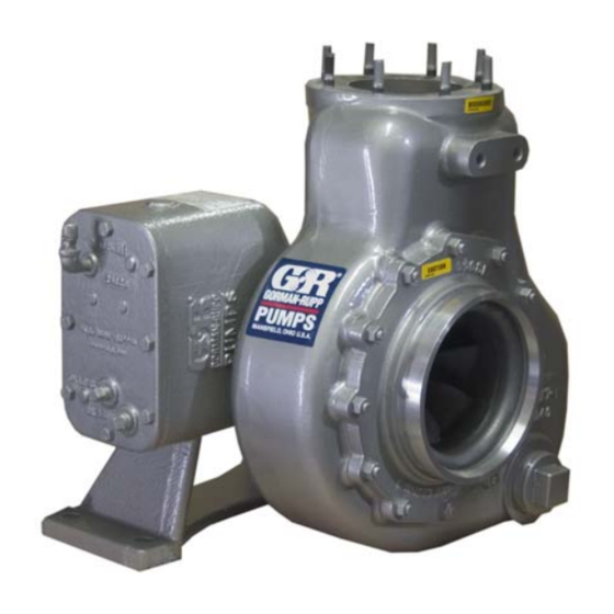
0 SERIES PUMPS
MODELS
06C1-GA
06C3-GA
THE GORMAN-RUPP COMPANY D MANSFIELD, OHIO
www.gormanrupp.com
D
GORMAN-RUPP OF CANADA LIMITED
ST. THOMAS, ONTARIO, CANADA
Printed in U.S.A.
e
Copyright by the Gorman-Rupp Company
Advertisement
Table of Contents

Related Manuals for GORMAN-RUPP PUMPS 06C1-GA


Summary of Contents for GORMAN-RUPP PUMPS 06C1-GA
- Page 1 October 1, 1992 Rev. A 05-04-06 INSTALLATION, OPERATION, AND MAINTENANCE MANUAL WITH PARTS LIST 0 SERIES PUMPS MODELS 06C1-GA 06C3-GA THE GORMAN-RUPP COMPANY D MANSFIELD, OHIO www.gormanrupp.com GORMAN-RUPP OF CANADA LIMITED ST. THOMAS, ONTARIO, CANADA Printed in U.S.A. Copyright by the Gorman-Rupp Company...
- Page 2 Register your new Gorman-Rupp pump online at www.grpumps.com/register. Valid serial number and e-mail address required. The engine exhaust from this product contains chemicals known to the State of California to cause cancer, birth defects or other reproductive harm. RECORD YOUR PUMP MODEL AND SERIAL NUMBER Please record your pump model and serial number in the spaces provided below.
-
Page 3: Table Of Contents
TABLE OF CONTENTS INTRODUCTION ..........PAGE I −... - Page 4 TABLE OF CONTENTS (continued) Pump Casing Removal ..........PAGE E −...
-
Page 5: Introduction
0 SERIES OM−01247 INTRODUCTION Thank You for purchasing a Gorman-Rupp pump. For information or technical assistance on the pow- Read this manual carefully to learn how to safely er source, contact the power source manufactur- install and operate your pump. Failure to do so er’s local dealer or representative. -
Page 6: Safety - Section A
0 SERIES OM−01247 SAFETY − SECTION A This information applies to 0 Series erating or servicing the pump. Provide adequate ventilation, prohibit smoking, power take-off driven pumps. Refer to wear static-resistant clothing the manual accompanying the vehicle shoes. Clean up all fuel spills immedi- before attempting to begin operation. - Page 7 0 SERIES OM−01247 cautions to ensure the area surrounding the pump is adequately ventilated. Al- low the pump to cool and use extreme caution when venting the pump, or Never tamper with the governor to gain when removing covers, plates, plugs, or more power.
-
Page 8: Installation − Section Bpage B
0 SERIES OM−01247 INSTALLATION − SECTION B Review all SAFETY information in Section A. coming pressure to 50% of the maximum permissi- ble operating pressure as shown on the pump per- Since pump installations are seldom identical, this formance curve (see Section E, Page 1). section offers only general recommendations and practices required to inspect, position, and ar- The integral gearbox is designed to be driven... -
Page 9: Preinstallation Inspection Page B
OM−01247 0 SERIES PREINSTALLATION INSPECTION VEHICLE REQUIREMENTS The following instructions apply equally to new in- The pump assembly was inspected and tested be- stallations, rebuilds or retrofits. fore shipment from the factory. Before installation, inspect the pump for damage which may have oc- Tank Preparation curred during shipment. - Page 10 0 SERIES OM−01247 sion jack with custom brackets should be When connecting the universal joint drive shaft as- sembly to a PTO unit, install, support, and align the used to lift and position the pump and drive shaft in accordance with the manufacturer’s gearbox.
-
Page 11: Suction And Discharge Piping
OM−01247 0 SERIES LUGS MUST BE IN LINE, REGARDLESS OF OPERATING ANGLE SHOWN BELOW LUG ALIGNMENT SHAFTS PARALLEL, ANGLES EQUAL SHAFTS NOT PARALLEL, ANGLES EQUAL Figure 2. Proper Installation And Alignment of Universal Assembly SUCTION AND DISCHARGE PIPING tors, related piping and safety accessories. Some of the accessories are available from Gorman- Rupp as optional equipment. -
Page 12: Piping
0 SERIES OM−01247 SCHEMATIC SYSTEM USING EDUCTOR FOR DISPENSING AND FILLING Figure 3. Typical System Installation Using Educator For Filling And Dispensing SCHEMATIC SYSTEM USING PUMP FOR DISPENSING AND FILLING Figure 4. Typical Installation Using Pump For Filling And Dispensing Piping A suction strainer was not furnished with this pump since it is not designed to handle liquids containing... -
Page 13: Sealing
OM−01247 0 SERIES suction line to ensure an adequate supply of liquid Sealing to the pump. Since even a slight leak will affect priming, head, and capacity, especially when operating with a high suction lift, all connections in the suction line should be sealed with pipe dope to ensure an air- tight seal. -
Page 14: Siphoning
0 SERIES OM−01247 Siphoning FDF valve to increase dispensing rates and im- prove efficiency. An eductor may also be used to Do not terminate the discharge line at a level lower collapse the tank service hose after the tank has than that of the liquid being pumped unless a si- been filled or emptied. -
Page 15: Operation − Section C
OM−01247 0 SERIES OPERATION − SECTION C Review all SAFETY information in Section A. Add liquid to the pump casing when: 1. The pump is being put into service for the Follow the instructions on all tags, labels and first time. decals attached to the pump. -
Page 16: Drive
OM−01247 0 SERIES pump could be damaged and performance ad- Overheating can occur if operated with the valves versely affected by incorrect rotation. If pump per- in the suction or discharge lines closed. Operating formance is not within the specified limits (see the against closed valves could bring the liquid to a curve on Page E−1), check the direction of rotation boil, build pressure, and cause the pump to rup-... -
Page 17: Stopping
OM−01247 0 SERIES Block the suction line and start the pump. At oper- After stopping the pump, switch off the vehicle igni- ating speed the pump should pull a vacuum of 15 tion and remove the key to ensure that the pump to 17 inches (381 to 432 mm) or more of mercury will remain inoperative. -
Page 18: Troubleshooting − Section D
0 SERIES OM−01247 TROUBLESHOOTING − SECTION D Review all SAFETY information in Section A. Before attempting to open or service the pump: 1. Familiarize yourself with this manual. 2. Switch off the vehicle ignition and re- move the key, or take other precau- tions to ensure that the pump will re- main inoperative. - Page 19 OM−01247 0 SERIES TROUBLE POSSIBLE CAUSE PROBABLE REMEDY Impeller or other wearing parts worn Replace worn or damaged parts. PUMP STOPS OR FAILS TO DELIVER or damaged. Check that impeller is properly cen- RATED FLOW OR tered and rotates freely. PRESSURE (cont.) Suction lift or discharge head too high.
-
Page 20: Pump Maintenance And Repair - Section Epage E
0 SERIES OM−01247 PUMP MAINTENANCE AND REPAIR - SECTION E MAINTENANCE AND REPAIR OF THE WEARING PARTS OF THE PUMP WILL MAINTAIN PEAK OPERATING PERFORMANCE. STANDARD PERFORMANCE FOR PUMP MODELS 06C1−GA AND 06C3−GA Based on 70_ F (21_ C) clear water (corrected to Contact the Gorman-Rupp Company to verify part 0.8 specific gravity) at sea level with minimum suc- numbers. - Page 21 OM−01247 0 SERIES SECTION DRAWING PARTS PAGE Figure 1. Pump Models 06C1−GA And 06C3−GA PAGE E − 2 MAINTENANCE & REPAIR...
-
Page 22: Parts List: Pump Model
0 SERIES OM−01247 PARTS LIST Pump Models 06C1−GA And 06C3−GA (From S/N 1005575 up) If your pump serial number is followed by an N", your pump is NOT a standard production model. Contact the Gorman-Rupp Company to verify part numbers. ITEM PART NAME PART... -
Page 23: Pump And Seal Disassembly And Reassembly
OM−01247 0 SERIES PUMP AND SEAL DISASSEMBLY 5. Close the suction and discharge AND REASSEMBLY valves. 6. Vent the pump slowly and cau- tiously. Review all SAFETY information in Section A. 7. Drain the pump. Follow the instructions on all tags, label and de- cals attached to the pump. -
Page 24: Suction Head And Wear Ring Removal
0 SERIES OM−01247 ing feet to ease reassembly. Move the pump and Use caution not to damage the pump casing bore gearbox to a clean, well-equipped shop for mainte- when removing the ring. nance and repair. Suction Head And Wear Ring Removal Use caution not to damage the pump cas- The wear ring (42) can be serviced by removing the ing when removing the wear ring. - Page 25 OM−01247 0 SERIES REASSEMBLY, followed by PUMP AND SEAL REASSEMBLY. Pump Casing And Wear Ring Installation Most cleaning solvents are toxic and flam- mable. Use them only in a well-ventilated area If the wear ring (38) was removed for replacement, free from excessive heat, sparks, and flame.
- Page 26 0 SERIES OM−01247 BELLOWS SEAL STATIONARY SPRING SEAT SHAFT ROTATING ELEMENT IMPELLER SHAFT IMPELLER SHIMS O-RING IMPELLER PUMP CASING RETAINER Figure 2. 25271−192 Seal Assembly Lubricate the stationary seat O-ring with light oil and install it in the groove in the stationary seat. Use thumb pressure to press this subassembly into the pump casing until fully seated.
- Page 27 OM−01247 0 SERIES 1.44 36,6 mm IMPELLER SHAFT SLEEVE 1.00 D 1.25 D SEAL 25,4 mm 31,8 mm AREA TAPER (APPROX.) KEYWAY FINISH ALL OVER TO ENDS TO BE SQUARE BE 50 RMS OR LESS AND PARALLEL SLEEVE DIMENSIONS SLEEVE INSTALLED Figure 3.
- Page 28 0 SERIES OM−01247 NOTE Install the suction and discharge lines and open all valves. Make certain that all piping connections are It is not recommended that substitute locking mate- tight, properly supported and secure. rials be used in this application. Use only the rec- ommended ‘Loctite’...
- Page 29 OM−01247 0 SERIES drive shaft and assembled bearing (27) from the Rotate the bearings by hand to check for rough- gearbox housing. Retain the woodruff key (16) and ness or binding and inspect the bearing balls. If ro- helical gear as they come free of the shaft. tation is rough or the bearing balls discolored, re- place the bearings.
- Page 30 0 SERIES OM−01247 NOTE Apply a light coating of oil to the lip of the oil seal (26), and press it into the bearing cap (23) with the If a hot oil bath is used to heat the bearings, both the lip positioned as shown in Figure 1.
- Page 31 OM−01247 0 SERIES NOTE the pump is operated continuously or installed in an environment with rapid temperature change. If the gearbox is rotated out of the standard posi- tion, the oil fill and drain plugs must be relocated. The magnetic drain plug (53) must be relocated to the lowest port, and the oil vent and elbow (12 and 13) must be relocated to the highest port.
- Page 32 For U.S. and International Warranty Information, Please Visit www.grpumps.com/warranty or call: U.S.: 419−755−1280 International: +1−419−755−1352 For Canadian Warranty Information, Please Visit www.grcanada.com/warranty or call: 519−631−2870 THE GORMAN-RUPP COMPANY D MANSFIELD, OHIO GORMAN-RUPP OF CANADA LIMITED ST. THOMAS, ONTARIO, CANADA...
Need help?
Do you have a question about the 06C1-GA and is the answer not in the manual?
Questions and answers