Table of Contents

Related Manuals for GORMAN-RUPP PUMPS 06D1-GA


Summary of Contents for GORMAN-RUPP PUMPS 06D1-GA
- Page 1 OM-01256-03 October 6, 1992 Rev. C 06‐11‐18 INSTALLATION, OPERATION, AND MAINTENANCE MANUAL WITH PARTS LIST 0 SERIES PUMPS MODELS 06D1‐GA 06D1-GAR GORMAN‐RUPP PUMPS www.grpumps.com 1992 Gorman‐Rupp Pumps Printed in U.S.A.
- Page 2 Register your new Gorman‐Rupp pump online at www.grpumps.com Valid serial number and e‐mail address required. RECORD YOUR PUMP MODEL AND SERIAL NUMBER Please record your pump model and serial number in the spaces provided below. Your Gorman‐Rupp distributor needs this information when you require parts or service. Pump Model: Serial Number:...
-
Page 3: Table Of Contents
TABLE OF CONTENTS INTRODUCTION ..........PAGE I - 1 SAFETY ‐... - Page 4 TABLE OF CONTENTS (continued) Pump Casing Removal ..........PAGE E - 5 PUMP AND SEAL REASSEMBLY .
-
Page 5: Introduction
0 SERIES OM-01256 INTRODUCTION Thank You for purchasing a Gorman‐Rupp pump. The following are used to alert maintenance per Read this manual carefully to learn how to safely sonnel to procedures which require special atten install and operate your pump. Failure to do so tion, to those which could damage equipment, and could result in personal injury or damage to the to those which could be dangerous to personnel:... -
Page 6: Safety - Section A
0 SERIES OM-01256 SAFETY - SECTION A This information applies to 0 Series power take‐off driven pumps. Refer to the manual accompanying the vehicle before attempting to begin operation. If this pump is used with volatile and/or flammable liquids, be certain proper Because pump installations are seldom safety practices are followed before op... - Page 7 0 SERIES OM-01256 deteriorate, and the liquid could come the emergency brake before attempting to a boil, build pressure, and cause the to disconnect the drive shaft or remove pump casing to rupture or explode. the pump. Be sure the pump is properly reinstalled and secure before opera...
-
Page 8: Installation - Section B
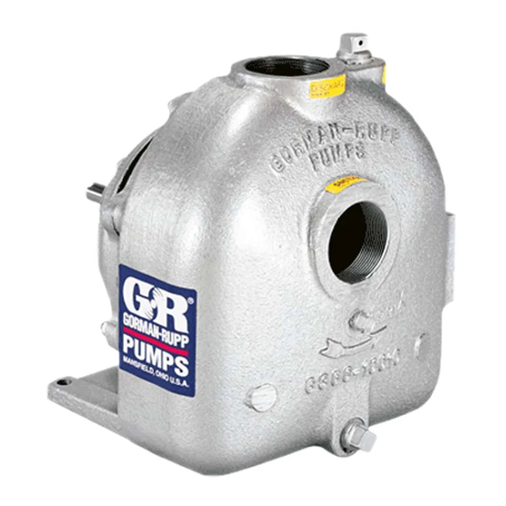
See Figure 1 for the approximate physical dimen Since the pressure supplied to the pump is critical sions of this pump. OUTLINE DRAWING Figure 1. Pump Model 06D1-GA INSTALLATION PAGE B - 1... -
Page 9: Preinstallation Inspection
OM-01256 0 SERIES OUTLINE DRAWING Figure 1. Pump Model 06D1-GAR PREINSTALLATION INSPECTION shaft will adversely effect pump perform ance, and the pump and/or gearbox could The pump assembly was inspected and tested be be seriously damaged. fore shipment from the factory. Before installation, d. -
Page 10: Tank Preparation
0 SERIES OM-01256 Tank Preparation NOTE If the gearbox is rotated out of the standard position shown in Figure 1, the oil fill and drain plugs must It is essential that any tank scale, dirt, or other for be relocated. The magnetic drain plug must be re eign material be removed from the tank and piping located to the lowest port, and the oil vent and el... -
Page 11: Suction And Discharge Piping
OM-01256 0 SERIES LUGS MUST BE IN LINE, REGARDLESS OF OPERATING ANGLE SHOWN BELOW LUG ALIGNMENT SHAFTS PARALLEL, ANGLES EQUAL SHAFTS NOT PARALLEL, ANGLES EQUAL Figure 2. Proper Installation And Alignment of Universal Assembly SUCTION AND DISCHARGE PIPING tors, related piping and safety accessories. Some of the accessories are available from Gorman‐... -
Page 12: Piping
0 SERIES OM-01256 SCHEMATIC SYSTEM USING EDUCTOR FOR DISPENSING AND FILLING Figure 3. Typical System Installation Using Educator For Filling And Dispensing SCHEMATIC SYSTEM USING PUMP FOR DISPENSING AND FILLING Figure 4. Typical Installation Using Pump For Filling And Dispensing Piping A suction strainer was not furnished with this pump since it is not designed to handle liquids containing... -
Page 13: Sealing
OM-01256 0 SERIES suction line to ensure an adequate supply of liquid Sealing to the pump. Since even a slight leak will affect priming, head, and capacity, especially when operating with a high suction lift, all connections in the suction line should be sealed with pipe dope to ensure an air... -
Page 14: Eductors
0 SERIES OM-01256 phoning action causing damage to the pump prove efficiency. An eductor may also be used to could result. collapse the tank service hose after the tank has been filled or emptied. Eductors Contact the Gorman‐Rupp Company or an author An eductor may be used in conjunction with an ized distributor for specifications and performance FDF valve to increase dispensing rates and im... -
Page 15: Operation - Section C
The pump will not prime when dry. Extended operation of The correct direction of pump rotation for pump a dry pump will destroy the seal assembly. model 06D1-GA is counterclockwise when fac OPERATION PAGE C - 1... -
Page 16: Drive
OM-01256 0 SERIES ing the input drive shaft. The correct direction of Liquid Temperature And Overheating pump rotation for pump model 06D1-GAR is clockwise when facing the input drive shaft. The The maximum liquid temperature for this pump is pump could be damaged and performance ad 160_ F (71_C). -
Page 17: Pump Vacuum Check
OM-01256 0 SERIES Pump Vacuum Check head, gradually close the discharge throttling valve before stopping the pump. Since this pump does not have a suction check After stopping the pump, switch off the vehicle igni valve, the discharge line must be fitted with a check tion and remove the key to ensure that the pump valve if a pump vacuum reading is to be taken. -
Page 18: Troubleshooting - Section D
0 SERIES OM-01256 TROUBLESHOOTING - SECTION D Review all SAFETY information in Section A. Before attempting to open or service the pump: 1. Familiarize yourself with this manual. 2. Switch off the vehicle ignition and re move the key, or take other precau tions to ensure that the pump will re... - Page 19 OM-01256 0 SERIES TROUBLE POSSIBLE CAUSE PROBABLE REMEDY Impeller or other wearing parts worn Replace worn or damaged parts. PUMP STOPS OR FAILS TO DELIVER or damaged. Check that impeller is properly cen RATED FLOW OR tered and rotates freely. PRESSURE (cont.) Suction lift or discharge head too high.
- Page 20 0 SERIES OM-01256 equipped) between regularly scheduled inspec PREVENTIVE MAINTENANCE tions can indicate problems that can be corrected Since pump applications are seldom identical, and before system damage or catastrophic failure oc pump wear is directly affected by such things as curs.
-
Page 21: Pump Maintenance And Repair - Section E
OPERATING PERFORMANCE. PERFORMANCE BASED ON WATER PERFORMANCE BASED ON PETROLEUM STANDARD PERFORMANCE FOR PUMP MODELS 06D1-GA AND 06D1-GAR Based on 70_ F (21_ C) clear water (corrected to Contact the Gorman‐Rupp Company to verify part 0.8 specific gravity) at sea level with minimum suc... - Page 22 OM-01256 0 SERIES SECTION DRAWING PARTS PAGE Figure 1. Pump Models 06D1-GA And 06D1-GAR PAGE E - 2 MAINTENANCE & REPAIR...
-
Page 23: Parts List: Pump Model
0 SERIES OM-01256 PARTS LIST Pump Models 06D1-GA And 06D1-GAR (From S/N 1005542 Up) If your pump serial number is followed by an “N”, your pump is NOT a standard production model. Contact the Gorman‐Rupp Company to verify part numbers. -
Page 24: Pump And Seal Disassembly And Reassembly
OM-01256 0 SERIES Before attempting to service the pump, switch off PUMP AND SEAL DISASSEMBLY the vehicle ignition and remove the key, or take oth AND REASSEMBLY er safety precautions to ensure that it will remain inoperative. Close all valves in the suction and dis Review all SAFETY information in Section A. -
Page 25: Removing Pump And Gearbox
0 SERIES OM-01256 Suction Head And Wear Ring Removal NOTE When appropriate recycling facilities are available, the user should recycle components and fluids The wear ring (42) can be serviced by removing the when doing any routine maintenance / repairs and suction head (44). -
Page 26: Seal Removal And Disassembly
OM-01256 0 SERIES PUMP AND SEAL REASSEMBLY If the gearbox requires disassembly, refer to GEARBOX DISASSEMBLY GEARBOX Use caution not to damage the pump cas REASSEMBLY, followed by PUMP AND SEAL ing when removing the wear ring. REASSEMBLY. Pump Casing And Wear Ring Installation Seal Removal And Disassembly If the wear ring (38) was removed for replacement, press the replacement ring into the pump casing... - Page 27 0 SERIES OM-01256 non‐oil based solvent and a clean, lint‐free tissue. Wipe lightly in a concentric pattern to avoid scratching the faces. Most cleaning solvents are toxic and Inspect the seal components for wear, scoring, flammable. Use them only in a well‐ven grooves, and other damage that might cause leak...
- Page 28 OM-01256 0 SERIES Inspect the pinion shaft (45) for distortion, nicks, not to damage the seal face. After installation, wipe scratches, or damage to the shaft keyway. Dress the seal face in a concentric pattern with a clean, small nicks or burrs with a fine file or emery cloth. If lint‐free cloth to remove any fingerprints.
- Page 29 0 SERIES OM-01256 Step 1 Step 2 Step 3 Figure 4. Centering Impeller Within Pump Casing With the correct thickness of impeller adjusting (44) until it seats squarely against the shoulder shims installed, apply `Loctite Primer Grade T', fol bore. lowed by `Loctite Retaining Compound No.
- Page 30 OM-01256 0 SERIES After removing the shafts and bearings, clean and GEARBOX DISASSEMBLY inspect the bearings in place as follows. When the pump is properly operated and main tained, the gearbox should not require disassem bly. Disassemble the gearbox only when there is evidence of wear or damage.
- Page 31 0 SERIES OM-01256 If the bearings, pinion or drive shafts require re the shafts, one at a time, until they are fully seated. placement, use a suitable puller to remove the This should be done quickly, in one continuous bearings. motion, to prevent the bearings from cooling and sticking on the shaft.
- Page 32 OM-01256 0 SERIES damage or roll the oil seal lip. Secure the bearing oil fill pipe plug (53). When lubrication is required, cap with the nuts (20). remove the air vent (13) and add SAE No. 90 non‐ detergent gear oil. Fill the gearbox until the oil level Position the bearing housing on a flat surface with reaches the bottom of the fill plug hole.
- Page 33 For Warranty Information, Please Visit www.grpumps.com/warranty or call: U.S.: 419-755-1280 Canada: 519-631-2870 International: +1-419-755-1352 GORMAN‐RUPP PUMPS...
Need help?
Do you have a question about the 06D1-GA and is the answer not in the manual?
Questions and answers